

TechnologyNovember 12, 2019
Diagnostics for EtherNet/IP industrial control networks
The Standard Network Diagnostic Assembly is the first step in adding enhanced diagnostic capabilities to CIP devices. A standard structure provides a consisten set of diagnostic information in devices, with a goal of minimizing the messaging and user programming necessary to get the information to where it’s needed.
As the number and variety of networked devices continues to grow, and network installations gain complexity, there is a growing need for better diagnostics in industrial control applications.
It’s well-known that the Common Industrial Protocol (CIP) has rich object models that provide information useful for many purposes, but the objects are typically organized by their functional role which results in the diagnostic data being spread throughout the various objects.
Clients can access this data through messages to the various objects, but it would be helpful if the diagnostic related data in each of those objects were accessible as a group and located at a well-known location in devices, in order to minimize the amount to messaging required to read them. Furthermore, it would be helpful if the content was discoverable by the client tool to account for the variability of device features.
This enables diagnostic analysis and prognostic systems to more easily utilize the data with minimal, if any setup and configuration by the user.
Enhanced standard diagnostics
The Standard Network Diagnostic Assembly concept provides an ability to create a scaled architecture where object diagnostic data can be “plugged” together to create a diagnostic structure tailored to options and varied features.
Over the last several years, a roundtable of EtherNet/IP Implementers has been working on enhancing standard diagnostics for EtherNet/IP. The diagnostics working group within the roundtable has created a scope of work document that describes a framework for common diagnostics for EtherNet/IP devices and the work items needed to realize the framework.
The purpose of the scope of work document has been to:
- Define common important terms and concepts related to EtherNet/IP diagnostics, to ensure a common understanding among project participants.
- Define the essential problems that the diagnostic effort needs to solve, including specification of a set of high-level requirements that the diagnostic framework should meet.
- Define use cases relevant to diagnostics.
- Define the scope of the diagnostic effort.
This effort includes the definition of diagnostic structures for various object classes to create specification-controlled diagnostic content that client tools can access. These structures are then referenced in an Assembly object that is located at an assembly instance that is common to all devices.
This Standard Network Diagnostic Assembly with specification-controlled content means that tools can always go to a known object address inside a device to obtain a consistent set of diagnostic information, without needing to send numerous messages to different CIP paths within the device. This provides for consistent content, in different devices from different vendors, that’s always at a common location.
The focus of the current work is to expose diagnostics related to the network health and device loading; also known as the Big 12 Network Diagnostics. However, this current work establishes the underpinnings that can support other types of diagnostic assemblies that can be utilized for more comprehensive diagnostics.
The need for diagnostics
There is a growing need for better diagnostics in industrial control applications. The IIoT phenomenon is bringing more and more devices to industrial networks. As the number and variety of devices grow, system complexity grows. As complexity grows, the need to more effectively manage these networks results in the need for information about the current operating state of the network. And when systems struggle to perform as they should, the diagnosis requires information from devices as well as the infrastructure that connects them.
It’s well-known that the CIP Networks Library’s rich object models provide information that is useful for many purposes beside the run-time exchange of control data. Specifically, many attributes of objects are reflective of device and/or system health. When analyzed in that context, this data provides insights into the device’s current operation such as loading, whether its network interface is functioning properly, and indications of how the physical later is performing, etc.
By trending changes to these indicators over time, it’s possible to discover potential system issues before the system degrades to the point of failure, thereby avoiding unplanned downtime. And when a system is experiencing problems, this information can be utilized by the system troubleshooter to determine what’s wrong and how to fix it.
Diagnostic challenges
There are several challenges with gathering diagnostic information in a control system. One is the amount of messaging needed. Today, diagnostic data is organized throughout various network related objects. This requires addressing different attributes in different objects with multiple messages. You must discretely read each one. For example, the data commonly referred to as The Big 12, is in ten different attributes of three different object classes. It requires 10 messages per device to retrieve them all.
If you extend this across an entire system, it is easy to see that it will require a significant amount of traffic to gather all this information. So minimizing the required messaging is desirable.
Another challenge is variation between devices. Most of the system attributes are optional, which opens the door for different vendors to implement different subsets of these attributes. Knowing which devices implement which subset of the diagnostic attributes means clients need to know ahead of time, which attributes are supported and which aren’t.
Furthermore, different features of devices such as number of ports, support for high-availability protocols, etc. have an impact on what network diagnostic data a device may have. User selections made when configuring a device can have similar impact. This requires clients to send unique message sets to different devices, which adds complexity, so organizing the data so its content is known is also desirable.
Customers are looking to spend less time dealing with network diagnostic data in control programs. A method that uses less messaging, is consistent across devices and where there’s variations, clients can discover them more easily, is what they want. The work to create a Standard Network Diagnostic Assembly was originally developed by the Roundtable, and is now in the hands of several ODVA Special Interest Groups (SIGs). It addresses these usability features for network related diagnostics by making diagnostic data readily available in all devices that support it, at well-known locations, with content that is defined by the spec and discoverable.
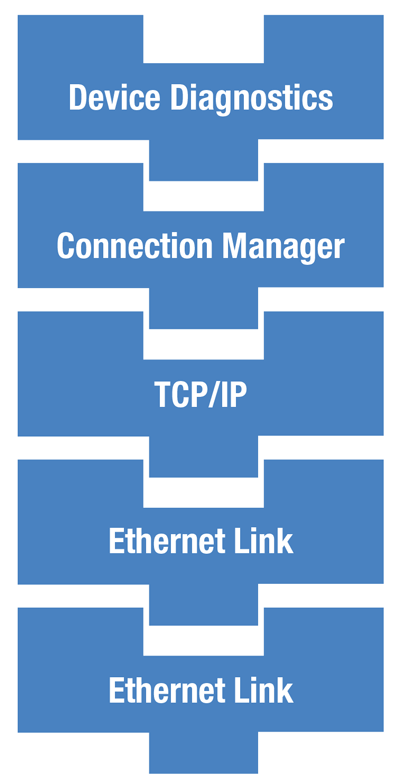
Even though these concepts are being developed for network diagnostics today, they can be easily extended to other device, security and system diagnostics later. The concept is intended to provide the ability to create a scaled architecture where various object diagnostic data can be “plugged” together to create a diagnostic structure tailored to device’s optional and varied features, as illustrated here. It’s anticipated that future work will include definition of device level diagnostics that deal more with diagnosing the status of application-specific objects.
Network diagnostic assembly
The goal for the Standard Network Diagnostic Assembly is to make it easier for diagnostic and prognostic analysis tools/systems to utilize data that is available in devices. It minimizes the traffic that’s needed to read all the information. It provides consistency and where variability exists; it helps identify the uniqueness and simplifies the job of interpreting information. This minimizes user programming impact, application development complexity, and has a low impact on devices on the network.
One new item for CIP is the creation of assembly instances that are defined for all devices. These are intended to make it easier for clients to find diagnostic information in devices and to retrieve the information with one message request. There is a range of assembly object instances (currently reserved by CIP) being allocated for use as “globally defined” assemblies that can exist in any device, regardless of type. What’s unique about these assembly reservations is that currently, assemblies in CIP are defined in Device Profiles, so this is the first profile-independent definition of assembly instances in CIP that have data applicable to any device.
The specification enhancements allocate 6 instances in the range of 0xD2-0xD7 for this purpose. These instances are being defined in Volume 1 of the CIP Networks Library, which is the volume that is common to all CIP network implementations. By doing this in the common volume, these assemblies can contain information about all network adaptations of CIP, and support devices like gateways and bridges.
The first instance in this range of assembly instances (instance 0xD2) is defined as the Standard Network Diagnostic Assembly. This assembly contains information about network health and device loading. Most of the diagnostic attributes used in this assembly come from the link objects associated with the network adaptations. For those familiar with the work that the Roundtable has been doing, this group of attributes for EtherNet/IP devices has been referred to anecdotally as “the Big 12 Diagnostic Attributes”.
Some objects in the device that have useful diagnostic information are only present when optional network functionality like time synchronization and high-availability protocols are enabled, or when devices implement different network functionality. These have also been added to the assembly to expand the list beyond just the 12 items, along with rules for placement of these within the assembly.
In support of the objective of creating a pluggable diagnostics architecture, the specification establishes rules that deal with the variability of devices. This variability can be illustrated with a simple example. A device with multiple Ethernet ports with a configurable embedded switch, that is user configurable for DLR or two separate Ethernet ports. When configured for DLR, there will be one TCP/IP structure, two Ethernet Link structures and a DLR structure. When configured as two separate Ethernet ports there will be two TCP/IP structures, two Ethernet Link structures and no DLR structure.
Rule specifying the ordering of members, whether the various structures are required or optional, and how many instances are permitted are found in the definition of this assembly. Furthermore, the Member List (Assembly Instance Attribute #2) is limited, and the Member List is not settable like it is for Dynamic assemblies. These rules will permit clients to know what to expect in the assembly for any network configuration it encounters.
These rules for the Standard Network Diagnostic Assembly make it slightly different than most assemblies. They are similar to static assemblies, but have some characteristics of dynamic assemblies as well. It is anticipated that a third type of assembly will be created in the specification to accommodate these differences. It’s believed that this is necessary to permit the Conformance Test to develop the tests needed to verify the unique behavior combination.
The Member List Signature (Class 4, Instance Attribute #5) that appears in the first position of the member list. This is a new instance attribute that is being added to the Assembly object definition. The value of this attribute is managed by devices as a way to indicate that the member list has changed. The value is either calculated or predetermined by the device, based on the member list content. If upon reading this attribute a client sees that the value has changed, it knows it must read and process the member list before attempting to interpret the Data Attribute (Assembly Instance Attribute #3). If the value remains the same, then the Data Attribute can be read and interpreted as it was previously. As a part of the Member List, the Member List Signature will be the first item returned in the Data Attribute so that the client receives both the signature and the content, in context. Therefore, by simply reading the Data Attribute, a client can easily detect changes in device configuration that have impacted the content of the assembly.
Standardized diagnostic data
Diagnostic data comes from attributes of objects. Recall from earlier, that not all the attributes are required in product implementations. This means that product developers are free to independently decide which ones to use and how to group them, if they are grouped at all. This results in variability between devices, which makes it harder for clients/tools that want to make use of the information to interpret the content.
Consider two devices, both with a single Ethernet port, but differing with respect to which diagnostic attributes they provide to the network. If we provided a standard assembly but no content standardization, a client tool would have to know how to interpret the structure of data from each device independently. They would either require prior knowledge, possibly gained from EDS file constructs describing the structure, or by some means of querying the device for the necessary information.
EDS is a possibly useful solution to this, however the clients/tools that are harvesting this information today, typically do not have the necessary infrastructure to host EDS files for all the possible devices it may encounter. Many of the clients are envisioned to be handheld devices that would not have the capacity to accomplish this. To address this, the object definitions for some of the more popular network related objects in the CIP Networks Library are being updated to add a section for diagnostic structures. The structures will consist of the attributes from the class that are determined to be useful diagnostic information. Over time, it is envisioned that other objects will be updated with similar information. The determination of what is useful diagnostic information will be made by the SIGs that have responsibility for the object class.
The intent for the kind of information present in the diagnostic structures defined by the object classes is to convey several kinds of information about the device:
- Values that, when they change, indicate there is a problem with the device that needs attention or that a previous problem has cleared or been corrected. For example, a Link Down indication for an Ethernet port, or the Connection Timeouts value.
- Values that indicate the current device loading. So for example, things like the number of TCP connections in use, the number of CIP connections that are open, I/O packet rates, and CPU Utilization, just to name a few.
- Values that are generally static like device settings, capabilities attributes, etc. and values that are constantly changing, like I/O packet counts, are not intended to be part of these structures.
An example that illustrates a typical structure is shown in below. This example comes from the Connection Manager object showing the items defined for that object class that meet the criteria for diagnostic information presented earlier.
Note the members are aligned so that 32-bit members align on 32-bit boundaries, and the overall structure is padded to a 32-bit boundary. This was discussed previously with respect to the overall assembly structure, but the alignment starts here in the structure definition.
Another important feature of diagnostic data is the ability for a device to convey information about the data that can be used to determine acceptable range, provide default values, scaling and help text. In CIP, this kind of “metadata” is provided for by using Parameter Object instances in the device. Parameter objects are designed to provide this kind of information about the attribute it refers to, so that clients can use this in creating user interfaces to the attribute value. EDS files can also provide this, but the desire is to not require EDS for this, as discussed earlier.
In order to accommodate this need, object classes implementing Connection Points will have available, a new CIP Common Service that will allow a client to obtain the list of EPATHs to the attributes contained in the structure. The service will return an array of EPATHs to these attributes. For devices that chose to implement Parameter Object instances for these items, the service will return EPATHs to the Parameter Object instances that are associated with the structure members. This permits the client to learn more about the attribute and to provide more user-pertinent information about them. This service will be optional, as is the use of Parameter instances.
Consider an example, where an analytics client has rules for interpreting a value of the Link Down attribute of the Ethernet Link object. When it finds a non-zero value for this attribute it can provide the user with a text string that comes from the Parameter instance that refers to the Link Down attribute. This string might direct them to the potential causes and remedies of a Link Down situation.
The Connection Point section being added to objects in the CIP Networks Library is described in Volume 1, Chapter 4 where all the general CIP Object Model requirements are described. Locating it in this part of the specification will generalize the definition of the Connection Points section for use by any object in any volume, potentially for purposes other than just diagnostic information. It also allows a way to establish uniform rules for how the connection point content is maintained. The Connection Manager, TCP/IP Interface, Ethernet Link, Device Level Ring, Time Sync and Parallel Redundancy Protocol object classes are being modified with Connection Points specifically for diagnostic purposes.
These diagnostic structures will be assigned an identifier. That identifier will be referenced using a CIP construct called a Connection Point. The Connection Point is familiar to most as a way to identify Class 0/1 transport connections for I/O data, however, the specification doesn’t limit their use to that purpose. Connection Points are being applied here as a way to address this structure of information in the Member List (Assembly Instance Attribute #2) of the Standard Network Diagnostic Assembly. The EPATHs in the Member List will contain Logical Segments for the Connection Points instead of separately listing the EPATHs to all the individual Class/Instance/Attributes that make up the structures.
Diagnostic data structures
With standard content comes the need to manage how the content can evolve over time, because it’s unlikely that the content defined initially will remain unchanged forever. Given the long service life of industrial products, it is likely there will be a mixture of older and newer devices on networks, and mixtures of older and newer clients. The specification enhancements will establish rules for maintaining and modifying these structures that clients can apply when using the data. Future modifications to the specification must follow these rules in order to achieve forward/backward compatibility, and provide for future needs that are not necessarily known today. These rules are summarized here.
Clients must: (1) use the connection point and the size together, to determine the content of the structure; (2) interpret only up to the size they know when they encounter a connection point larger than they understand and; (3) expect and accommodate a mix of new/old servers.
These rules establish client behaviors, to allow for extending and modifying the structures over time, as the need arises.
Furthermore, future modifications to the structure definitions in the specifications must follow certain rules designed to aid in future extensibility. These rules are: (1) existing connection points can only be extended by adding members; (2) when a structure definition is extended, the size of previous version(s) must be maintained in the structure definition so that clients know all the valid size(s) for a given connection point; and (3) members of an existing connection point cannot be removed/replaced. If this is necessary, then a new structure with a new Connection ID must be defined.
These rules are designed to keep older clients and older devices viable, as these structures evolve. There are also rules for devices to follow when implementing these structures, to assure that clients can understand the content of the structures. These are: (1) if a device implements a structure, it implies that the device supports all members defined for that structure, even if the attributes themselves are defined as optional or conditional in the object definition; (2) implementations are not permitted to omit or replace with fill bytes, any member of the structure; and (3) implementations may not add any other members to the structure.
Diagnostic profiles
Something that is in the scope of the diagnostics working group in the Roundtable, but not part of the work to add the Standard Network Diagnostic Assembly, is the concept of Diagnostic Profiles that specify certain level(s) of required implementation of diagnostic capabilities. The profile(s) is designed to promote interoperability, by establishing basic levels of implementations for devices. The profile(s) will dictate what diagnostic content is required and what is optional in devices, which will guide product manufacturers toward implementing consistent features. This profile will also provide testing criteria for the Conformance Authority, which opens the door for ODVA to potentially verify the elevated level(s) of functionality.
It is anticipated that the Standard Network Diagnostic Assembly would be the base level of diagnostic profile with other levels developed later to include things like diagnostic event logging, product application diagnostics, user configurable diagnostic events, high/low water marks, logging, time stamping, etc.
Summary
The Standard Network Diagnostic Assembly is the first step in adding enhanced diagnostic capabilities to CIP devices that includes scalable diagnostic content that accommodates the feature variations in devices.
The Roundtable of EtherNet/IP Developers set out to define a standard network diagnostic structure that provides a consistent set of network diagnostic information in devices. The goal was to minimize the amount of messaging and user programming necessary to get the information to where it’s needed. The structure defined is extensible to account for device variability, and is located at a well-known and consistent location in all devices, so tools know where to get it.