

TechnologySeptember 20, 2021
Safeguarding PTP Protocol with Parallel Redundancy Protocol
This article shares a high-level view into PRP, PTP, and how one safeguards the other. The complex nature of today's industrial networks relies on a deep understanding of protocols' specifications and network design best practices.
Industry is embracing industrial automation to bring new and better services and to protect their critical infrastructures. In the process, they are quickly realizing the need for a secure and resilient industrial grade network. One of the key requirements from this network is to achieve time synchronization with high accuracy across crucial functions. The network needs to deliver the robust protocols that can handle both unexpected and planned events while shielding the complex systems and services that it supports.
Two key protocols answer the call for high precision time synchronization and enhanced redundancy – Precision Time Protocol (PTP) and Parallel Redundancy Protocol (PRP). PTP establishes a dynamic packet-based time synchronization mechanism that achieves sub-microsecond accuracy. PRP increases infrastructure reliability by providing lossless failure redundancy using two parallel networks and packet duplication.
Each of these protocols brings enormous value to industrial use-cases. Both integrate their operation over Local Area Networks (LANs). Both protocols utilize Local Area Networks, lower the cost of deployments and reduce overall network complexity. Industry verticals that can most benefit include telecommunications, financial, manufacturing, and energy sectors, among others. All of these require high availability, reliability, and highly accurate time synchronization to ensure services consistency.
Implementing PTP over a PRP environment isn’t as simple as combining both protocols. PRP’s redundancy works on packet duplication over parallel ethernet networks. PTP time synchronization accuracy relies on a clear understanding of path and transit delays.
Duplicating PTP packets would complicate the delivery of accurate timing information, potentially confusing end devices. Standards bodies introduced protocols’ modifications that eliminate these challenges, ensure their smooth coexistence, and help to highlight the advantages of their combined strengths.
This article shares an overview of how PRP interoperates with PTP and vice versa. Let’s start with a high-level view of PTP and PRP to set a baseline.
Precision Time Protocol (PTP)
Precision Time Protocol (PTP) is a time precision and synchronization protocol standardized by the IEEE in IEEE Std. 1588. PTP, a message-based protocol, runs on packet networks, such as Ethernet networks. It enhances the time synchronization mechanisms (phase, frequency, absolute time) from older, less accurate implementations to one that takes advantage of a Local Area Network where data and synchronization would use the same network infrastructure while providing sub-microsecond accuracy.
PTP automatically establishes a timing hierarchy. This allows network devices to protect timing accuracy by participating in its measurement and adjustment. Other older, less accurate time synchronization methods relied on their own dedicated infrastructures for analog and serial mechanisms, e.g., PPS (pulse per second) and IRIG-B used pulsed electrical signals or serial data grams. In the realm of data packet networks NTP (Network Time Protocol), also works over Ethernet and provides packet-based timing, but with lower precision. Its distributed implementation doesn’t account for the timing impact of network elements in the path between timing source and destination – PTP does.
Why is PTP important?
PTP integrates time synchronization services into the same industrial data Ethernet network where industrial devices communicate. The benefits of using PTP in an Ethernet network include low cost, ease of implementation, and the reduction of overall network complexity. It enhances support and serviceability and makes the infrastructure more reliable and secure.
The timing precision that PTP provides, aligns with the stringent requirements demanded by industrial automation and modernization efforts. It’s sub-microsecond precision is a critical component of automation and control systems, measurement and test systems, power generation, transmission and distribution systems, etc.
PTP is uniquely positioned to satisfy the need for these critical infrastructures (manufacturing, utilities, oil & gas, transportation, others) to accurately monitor their network, predict and protect from critical situations, and measure the delivery and consumption of services.
PTP inner workings
The standard defines a Master-Slave hierarchy with roles, port states, and related behaviors. As a side note, there is an ongoing effort by the standard bodies (IEEE, IEC, others) to find alternate terms to the controversial Master-Slave terminology. In this document we will use Master-Follower.
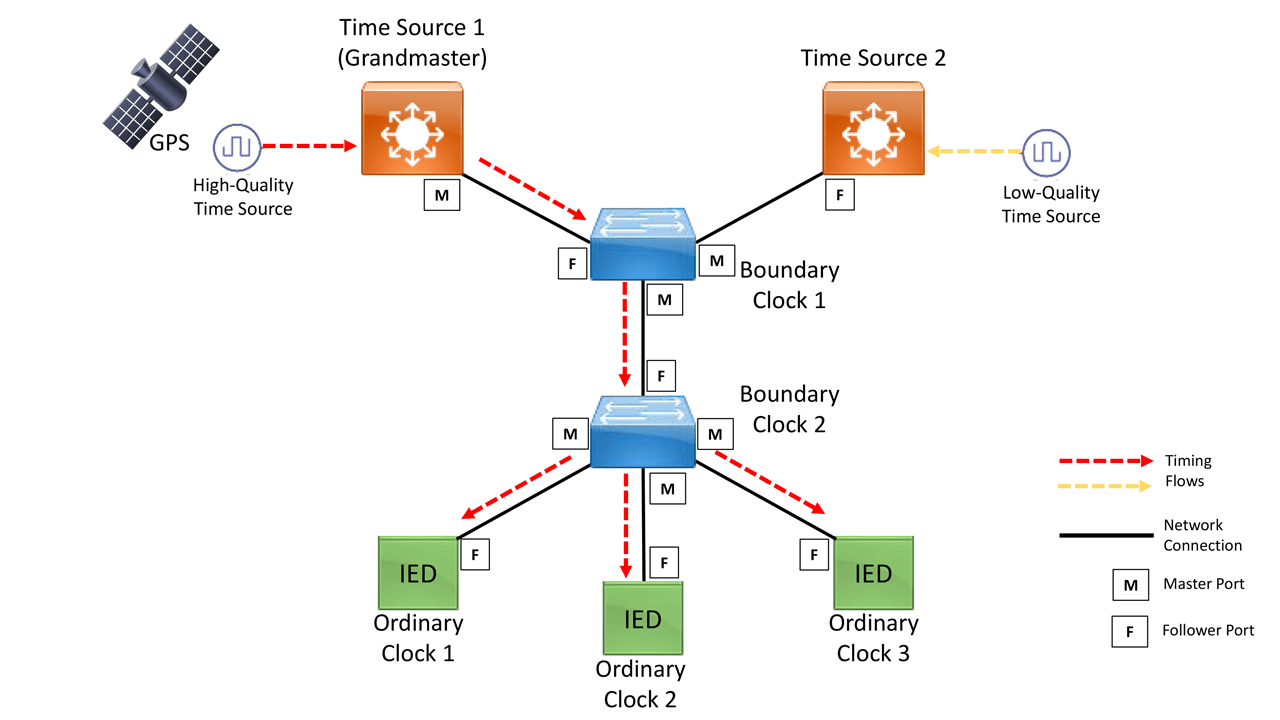
During and after the Master-Follower hierarchy is established, PTP timing synchronization messages traverse the network to calculate time delay differences on the path from the Master to the Follower Clocks and PTP entities in between, Figure 1 at the top of this article. These time delay calculations provide PTP devices with an accurate way to update their local clocks. The result is PTP’s sub-microsecond time synchronization precision.
A PTP network consists of PTP-capable devices, Clocks, and often, devices not using PTP. Though PTP communication happens between Master Clock(s) and Follower Clock(s), these are executed in a variety of roles providing key functionality along the way.
The following are roles in a PTP network (Clock types):
Grandmaster Clock (GM): primary time source for the hierarchy with either an external time source (e.g., GPS) or a very high accuracy internal time source. Could be a LAN switch.
Boundary Clock (BC): clock source that has more than one network port – normally a LAN switch. One or more ports receiving timing while others (one or more) sending time out. Follower to the Grandmaster Clock.
Ordinary Clock (OC): End-client device. Typically, with one network port to receive time. Industrial devices, sensors, relays, monitoring and metering systems (e.g., IEDs) Follower to the Grandmaster Clock.
Transparent Clock (TC): more than one network port – normally a switch, it updates the time interval field within the PTP event messages. This compensates for any switches in the path giving the timing messages accuracy within one picosecond. Follower to the Grandmaster Clock.
Each of these PTP-capable devices engage in establishing the Master-Follower hierarchy. Ports are not only used to connect these devices to the network but play an important part in the PTP state machine. There are three PTP port states:
Master (M) Port: port used to source clock information and messaging to downstream PTP devices (e.g., Followers)
Follower (F) Port: port used to receive the clock synchronization messages and update the Follower local clock after computing the delay of the link, time offset, frequency offset, and drift error parameters.
Passive Follower (PF) Port: port used to receive the clock synchronization messages but doesn’t update the local clock.
At a high-level, PTP dynamics can be grouped in two areas: Master Clock selection into the Grandmaster Clock role and ongoing PTP execution through the network to maintain full understanding (synchronization) of time and timing differences.
Multiple devices could be capable of becoming Master clocks. A mechanism to select the best Master Clock is known as Best Master Clock Algorithm (BMCA). During the execution of BMCA, clocks will evaluate the quality, stability, logical distance to the clock source and determine the top or best Master Clock (i.e., Grandmaster Clock).
In its simplest form, PTP exchanges can be summarized as follows:
- PTP messages sent between Master and Follower devices to determine delay.
- PTP measures the exact time messages are transmitted and received. It uses this information to determine the delay between devices to calculate an average path delay.
- Follower devices will adjust the received time based on the calculated path delay
Users can configure PTP in a multi-vendor environment. Cisco Industrial Ethernet products support multiple variations of PTP (e.g., profiles, versions) in all roles and combinations (hybrid modes). Cisco IE switches have a rich feature set with solid PTP support covering many industrial use-cases. Key platforms like the Cisco IE5000 can operate as a Grandmaster Clock thanks to its internal GPS receiver and accurate internal Oven-controlled crystal oscillator (OCXO). It also supports hybrid modes, e.g., Grandmaster Clock and Boundary Clock simultaneously. This allows for the convergence of services in a highly reliable industrial platform.
The use-cases and strict requirements of a critical network infrastructure will dictate the best option to support stringent time synchronization and precision needs. PTP is considered the most vital modern timing protocol for its flexibility, automation, and precision. Providing a reliable and resilient infrastructure is critical. This topic opens the door to our PRP conversation.
Parallel Redundancy Protocol (PRP)
PRP is defined by the International Standard IEC 62439-3. The protocol is designed to provide lossless or hitless redundancy across Ethernet networks for industrial applications. This zero-recovery time after failures sets PRP apart from traditional Ethernet network redundancy protocols such as Spanning Tree, where a network failure results in topology changes that disrupt traffic flow momentarily.
PRP provides a different approach to traditional data network redundancy. Redundancy is implemented at the PRP-node level instead of relying entirely on the data network devices. PRP lossless resiliency is achieved by connecting to two separate, independent, Local Area Networks (LANs) and duplicating traffic across said networks. A PRP dually attached node (DAN) transmits two packets simultaneously across LAN A and LAN B. At the receiving PRP endpoint a discard algorithm is in place to eliminate the duplication and deliver a single packet to the upper layers – to the applications.
Each PRP-frame, duplicated across LANs, is appended with a Redundancy Control Trailer (RCT) containing a sequence number, LAN ID, etc. This RCT enables the receiving node to identify and discard the duplicated messages.
Important point to highlight is that PRP redundancy is implemented at a PRP-node level. PRP-nodes are defined as follows:
Dually Attached Node (DAN): PRP node with two interfaces connecting to LAN A and LAN B respectively. PRP duplicates packets on transmission and removes duplication on receival.
Singly Attached Node (SAN): non-redundant endpoint, attaches to LAN A or LAN B. Needs to rely on other methods for PRP protection (e.g., RedBox) or remain unprotected.
Redundancy Box (RedBox): PRP device used to connect non-PRP endpoints into LAN A and LAN B thus providing PRP protection on behalf of the device. RedBox handled duplication for the devices behind it. The RedBox is a DAN.
Virtual DAN (VDAN): non-PRP endpoint connected into a RedBox appears as a “DAN” to other nodes in the PRP network. These are known as Virtual DANs (VDAN).
During a failure, LAN A in Figure 2 goes down or is impaired, the path for red packets is disrupted. This leads to red packet loss or extreme delays. However, the unaffected path, LAN B, will allow for the other duplicated packets, green, to arrive uninterrupted. The applications in the upper layer will not detect or “feel” any impacts due to the failure.
Cisco IE switches support a scalable and top performing deployment of PRP. The switches implement RedBox functionality allowing for a scalable number of VDANs (non-PRP endpoints) to be protected by PRP’s lossless redundancy.
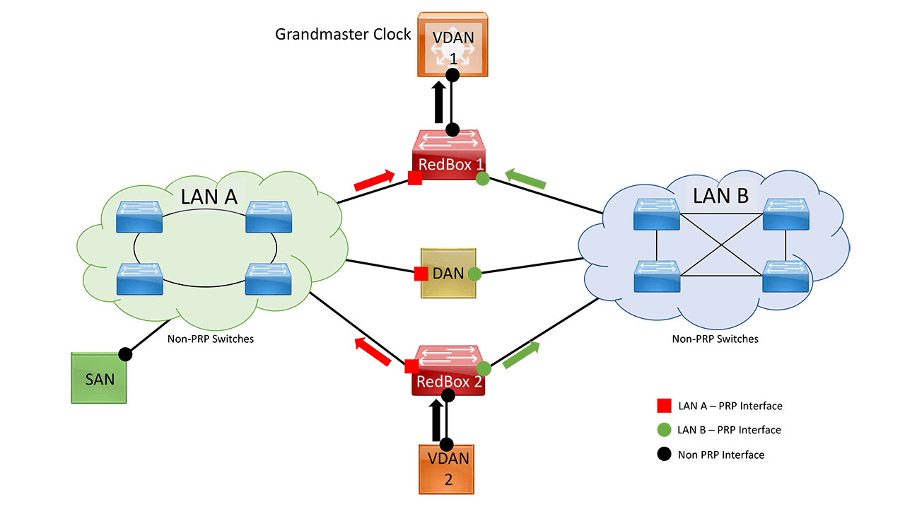
Figure 2. PRP Network (Traffic Duplication Flow)
PTP over PRP
Precision Time Protocol (PTP) can operate over Parallel Redundancy Protocol (PRP). PRP provides high availability through redundancy by parallel transmission over two independent networks. PTP and PRP can coexist in network devices and end-nodes. This coexistence allows PTP to take advantage of the redundant connections of PRP-nodes thus increasing its resiliency and reliability.
Why is this important? Precise time synchronization is a key foundational requirement for many industrial critical infrastructures. It drives precision alignment for key management, control, and serviceability functions. A failure could result is business, services, revenue, or quality of life disruptions. Safeguarding PTP with PRP protects business continuity. PTP over PRP is a practice that has generated a lot of interest in the industry.
The Original Challenge
The PRP method of achieving redundancy by connecting to two parallel networks (e.g., LAN A and LAN B) and duplicating each packet, one for each LAN does not work for PTP as it does for other traffic. Challenges included:
- The delay experienced by a frame is not the same in LAN A as in LAN B. Each LAN could have different topologies, traffic loads, types of network nodes.
- Some frames are modified in the Transparent Clocks (TCs) while transiting through the LAN.
- A Dually Attached Node (DAN) does not receive the same PTP message from both ports even when the source is the same.
- Boundary Clocks (BCs) present in the LAN are not PRP-aware and would generate their own PTP messages with no Redundancy Control Trailer (RCT) appended.
- Transparent Clocks are not PRP-aware and not obliged to forward the RCT, the message part after the payload.
The Solution
For PTP to take advantage of the redundancy benefits offered by the underlying PRP infrastructure, PTP packets need to be handled differently from other traffic types. The behavior required is detailed in IEC 62439-3:2016 standard, Annex A.
Cisco IE switches follow this IEC standard and implement an approach that overcomes the challenges mentioned above. Two high-level changes accomplish this:
1. PTP packets are not to be appended with PRP’s RCT (Redundancy Control Trailer)
2. PTP packets bypass PRP’s duplication and discarding logic (i.e., no duplication of PTP messages).
Basic PRP packet handling at DAN (non-PTP vs. PTP):
| Non-PTP Packets | PTP Packets |
|---|---|
| Upper layers (application) to generate 1 frame. | Separate PTP process per port (LAN A and LAN B). Time processing to be handled per port. |
| PRP logic to duplicate each upper layer frames into packets to be sent out each port (LAN A and LAN B). | PRP Stack will not duplicate PTP messages as those will bypass the stack. |
| Each duplicated packet to be appended with a Redundancy Control Trailer | No RCT to be appended to any PTP packet. |
PTP will follow the standard specifications for timing and synchronization over redundant ports which applies to PRP-nodes and makes the integration a valuable architectural foundation for industrial networks. In simple terms, PTP redundant ports will run separate PTP processes that listen for timing information from the Grandmaster Clock (i.e., Follower and Passive Follower ports). These will determine PTP communication status and local clock synchronization based on Grandmaster’s timing qualities.
These differences in regular vs. PTP packet handling dig into PRP’s actual behavior and the adjustments needed for timing and synchronization operations. The combination allows for concurrent protection of end-to-end services and the required timing precision that PTP offers. Next, a high-level example will expand on the cooperative behaviors.
Behavior
PRP nodes participating in timing synchronization will execute a separate virtual clock process (PTP process) per LAN A and LAN B port that needs to synchronize to the Grandmaster Clock. As mentioned earlier, this is one of the necessary modifications to PRP – eliminating duplication and discarding of said duplicate PTP packets.
On the other hand, all other traffic will be handled as defined by PRP’s standard in PRP-capable nodes (duplication, discarding of the second packet copy on arrival, appending RCT providing PRP with required information).
Figure 3 shows the different PTP processes that will run a simple PRP network. The yellow arrows represent the PTP messages behind the RedBoxes (Boundary Clocks in this example) towards the VSANs. Each redundant port on the RedBoxes will run a separate PTP instance / state-machine which will traverse each LAN. PTP in LAN A is represented by blue arrows and in LAN B by green arrows.
RedBox1 and 2 are Dually Attached Nodes (DANs). Each transmits and receives PTP information over both PRP ports connected to LAN A and LAN B. This behavior separates PTP communications, LAN A and LAN B, represented by green and blue arrows. FYI, ports where the DANs, SANs, and RedBoxes are acquiring GM’s timing information as labeled Master(M). Other ports transmitting timing information (PTP messages) to endpoints down the line are labeled Follower(F).
We remember that PRP’s redundancy is based on packet duplication across two parallel LANs. However, PTP operates outside of said duplication and relies on the protocol’s behavior over redundant links. PTP port status towards the Grandmaster clock is either Follower(F), in the case of a single PTP port (e.g., PTP capable SAN) or Follower(F) and Passive Follower(PF) when two PTP and PRP ports are connected to separate LANs.
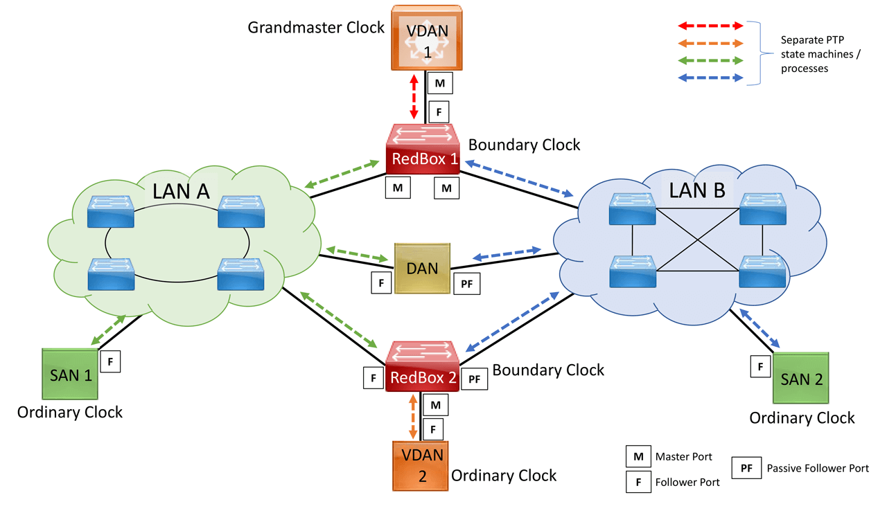
Figure 3. PTP traffic over PRP environment
Protection during a failure
In a failure, the second most noticeable change in PTP over PRP’s behavior becomes critical. Following Figure 3, RedBox1 and 2 elected LAN A ports as the PTP Follower ports from which they are synchronizing their clocks with the Grandmaster (GM) Clock (VDAN1).
Ports connected to LAN B are in a Passive Follower status (listening to PTP messages from the GM but not synchronizing their local clocks). If LAN A goes down, the LAN B ports in the DANs and RedBoxes take over as Follower (from Passive Follower state) and start to synchronize the local clock. VDANs (e.g., VDAN2) continue to receive PTP synchronization from their corresponding Redbox before the failure – slight operational difference if the Redbox is a Boundary vs. Transparent Clock. Note that for SANs, redundancy is not available. In this example, SAN 1 will lose synchronization if LAN A goes down.
Due to the change, VDAN2 may experience an instantaneous shift in its clock due to the offset between the LAN A port’s virtual clock and the LAN B port’s virtual clock. The magnitude of the change should only be a few microseconds at the most because both virtual clocks are synchronized to the same GM. In recovery, a shift occurs when the LAN A port comes back as Follower and the LAN B port becomes Passive Follower.
This scenario can be considered the baseline of PTP over PRP operations. Different use-cases will call for higher complexity levels depending on scalability and performance needs. Cisco Industrial solutions offer best practices for many viable industrial scenarios while keeping PRP, PTP, and their coexistence a simple configuration step. Cisco IE products provide top performance, market-leading resiliency options, practical support, and serviceability for industrial scenarios that increase infrastructure efficiencies while reducing operational expenses.
Closing words
PRP’s enhanced redundancy mechanisms establish a paradigm in network resiliency where lossless communication during failures safeguards the end-to-end transport of industrial services. These critical infrastructures rely on high levels of business continuity where resiliency and security are paramount, but so is the unquestionable dependency on high precision timing synchronization. PTP is the protocol that robustly provides dependable time precision.
That is why standards bodies like IEC have established detailed specifications on the integration of PRP and PTP. It is also why Cisco Industrial Ethernet products deliver proper support for both protocols with unrivaled solutions for end-to-end industrial critical infrastructures implementations.
Carlos Gonzalez, IoT Technical Marketing Engineer, Cisco
