


TechnologyJuly 1, 2020
Single-Pair Ethernet for constrained devices


Single Pair Ethernet offers reduction in wiring, node cost, size and power consumption, delivering communication and power over a single pair. New operational concepts are being developed to drive EtherNet/IP deployment to low-end constrained, in-cabinet devices such as contactors and push buttons.
A new set of operational concepts and technologies are being developed to drive successful EtherNet/IP deployment to many low end constrained devices or “Things” such as contactors and push buttons. This development could help enable a single-network vision where all devices in an industrial plant can communicate with the same set of protocols, while balancing node cost, node size, and ease of commissioning the smart system.
Industrial Ethernet has exhibited rapid growth, with EtherNet/IP emerging as a leader. The reality is that fieldbuses and sensor networks still retain a large position and many potential network nodes remain hardwired. End users understand and seek the advantages of a harmonized network based on EtherNet/IP, and the related open ecosystem. Benefits include reduced complexity and cost by minimization of gateways and elimination of hardwiring, expansion of the qualified labor pool, and improved optimization and maintenance opportunities via Cloud connectivity and analytics.

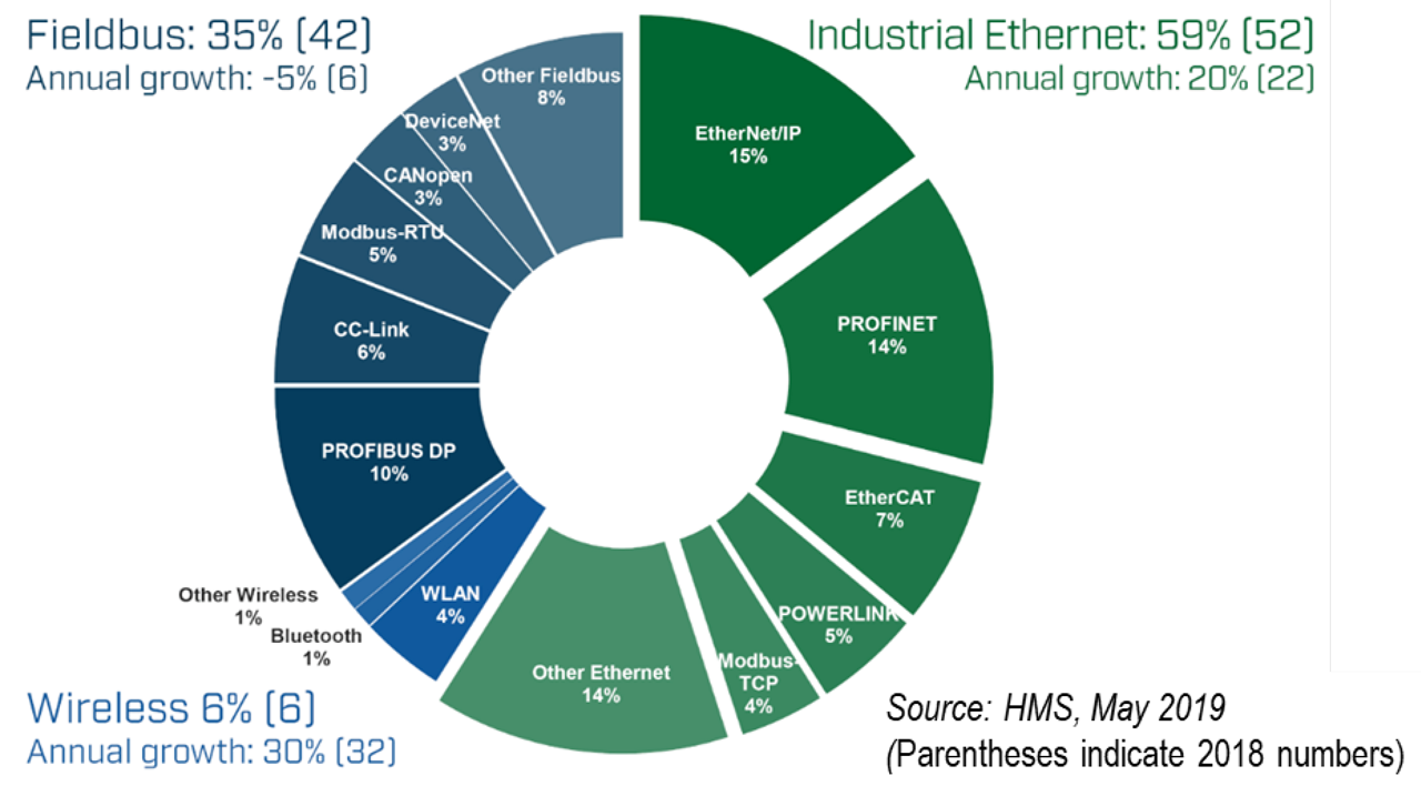
Industrial Ethernet solutions have been growing. Fieldbus and sensor networks form a shrinking portion.
With these benefits numerous industries have flooded into IEEE to develop enhancements for enabling Ethernet to displace other networks at the edge. The resulting Single Pair Ethernet suite offers reduction in wiring, node cost, size, and power consumption, delivering communication and power over a single pair.
A deterministic Ethernet bus variant targets very constrained devices, such as in-cabinet components. In prior years, we proposed a set of enhancements, adopted from or inspired by IETF and IEEE, to extend EtherNet/IP into constrained applications, further enabling the single network vision.
With an operational concept and IEEE P802.3cg, the current standard and probable follow-on for T1S PHY specification upgrades will expand the market for PHYs, SIG work in the EtherNet/IP System Architecture Special Interest Group and EtherNet/IP Physical Layer Special Interest Group covering UDP-only, capability discovery, profile concepts and modular additions of PHYs, cables, connector, and profile concepts.
The single network vision

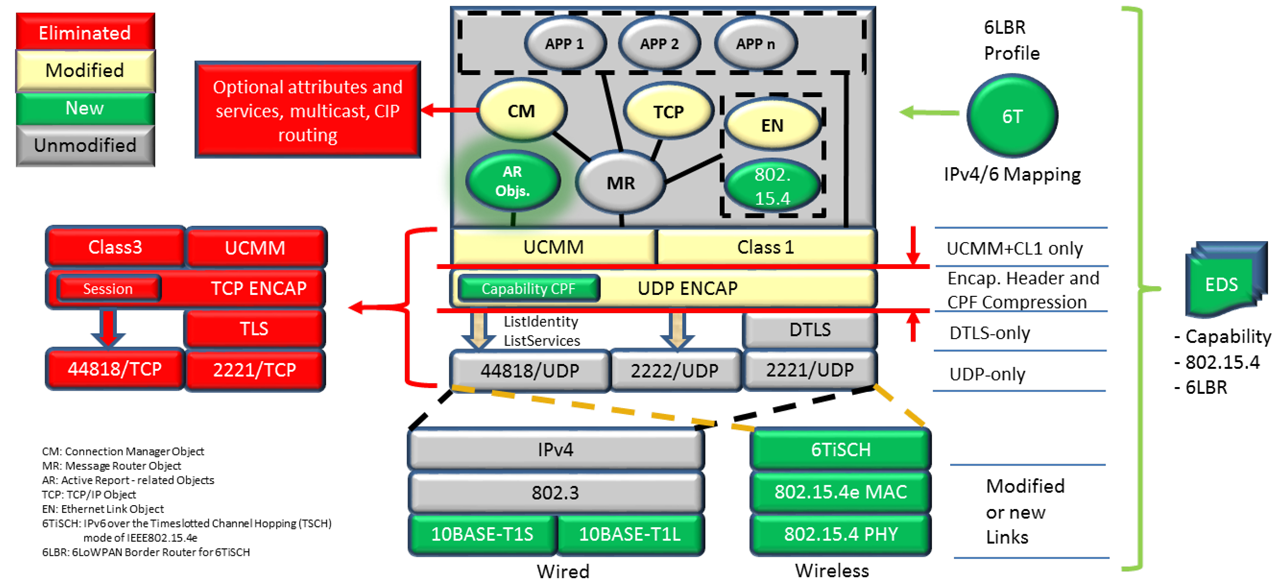
Figure summarizes the constrained EtherNet/IP proposal. Features in red are eliminated. Features in green are new additions. Features in yellow are modified (reduced).
Many end users understand and are seeking the advantages of a harmonized network based on Ethernet, Internet Protocol (IP), and the related open ecosystem. This desire is expressed within organizations across many industries.
The Automotive industry has been working toward an all-Ethernet vehicle. The industry formed the OPEN (One Pair EtherNet) Alliance to promote a variety of Single Pair Ethernet (SPE) solutions. Ethernet now pushes to the edge to displace other networks in the vehicle.
The Digital Ceiling partner ecosystem is promoting Ethernet-based smart LED lighting and associated sensors for occupancy, security, etc. Process Automation end users (NAMUR) demanded Ethernet and IP-based automation protocols for instruments and related devices. The Advanced Physical Layer (APL) organization, including ODVA and their peer organizations are responding with solutions.
IEEE continues to extend the standards for Single Pair Ethernet (SPE) to meet the specialized needs at the edge. These initiatives exist due to compelling advantages of a single network:
- Higher performance for a similar cost (compared to the displaced networks)
- Elimination of application-level gateways
- Leverage of a large existing ecosystem (protocols, security, network switches, etc.)
- Reduced installation, maintenance, and management complexity
- Simplified integration with cloud applications
- Reduced interoperability issues
IEEE contributions
Within IEEE, a family of Single Pair Ethernet (SPE) standards has been developed. These enable communication and optional power over a single pair, facilitating reduction in wiring, node cost, size, and power consumption. Early SPE standards included 100BASE-T1 (100 Mb/s), 1000BASE-T1 (1000 Mb/s), and optional power known as PoDL. In February of 2020, another family member was released: IEEE Std 802.3cg-2019. The new standard introduces a pair of 10 Mbit/s SPE PHYs that are targeted for constrained applications. Numerous industries sought Ethernet enhancements to displace edge networks and contributed to the standard. IEEE Std 802.3cg-2019 includes the following 2 PHYs.
10BASE-T1L
- Addresses long distance
- Targeted at process instruments
- 1000 m, intrinsic safety compatible, legacy wiring
10BASE-T1S
- Addresses low cost control
- Targeted at replacing: CAN, CAN FD, MOST, and FlexRay protocols in automotive; Hardwired components for in-cabinet industrial automation; I2C and SPI in data centers
- 25 m multidrop option
- Determinism by PHY-level Collision Avoidance (PLCA) protocol
Constrained EtherNet/IP applications

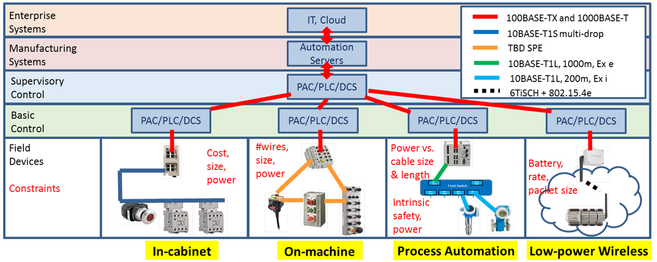
Candidate constrained application areas for EtherNet/IP.
Several new application areas are being targeted for EtherNet/IP at the network edge. These are constrained applications for field devices. From basic control, up through the enterprise, 100BASE-TX Ethernet and emerging 1000BASE-T Ethernet is suitable and likely to remain in place. At the field level, these are not well suited to meet the listed constraints.
Constrained EtherNet/IP application areas include Process Automation and the related application area of Low-power Wireless. They also include On-machine components. Each has unique constraints. Another important application is In-cabinet components. Here the transition is primarily from hardwiring to networked devices. Very strict constraints exist for low cost, small size, and low power.
Constrained in-cabinet devices
The following section covers the Constrained In-Cabinet Device viewpoint and describes how the Single Pair Ethernet technology can be applied in this space. The amount of control power (24VDC) wiring required to control pilot devices (such as push buttons, indicator buttons, contactors, etc.) is substantial. The wired connections, typically referred to as “hard wired connections”, supply control power to the pilot devices for operation.
The number of wires for a simple in-cabinet application would require numerous hours for commissioning and is error prone if needed to be replicated. Once commissioned, “hard-wired” systems for industrial applications create a high overhead for maintenance including, component updates or troubleshooting errors during operation or commissioning process while providing little to no intelligent data for analytics.
Constrained in-cabinet requirements
Based on the constrained in-cabinet device problem space, following are extracted key customer requirements based on extensive customer listening sessions:
Economical
- Low cost media
- Allow for a reduction in price and size of typical products
- Allow the use of commercial off-the-shelf power supplies
- Result in a lower “total cost of ownership” than hard-wired solutions
Simple to use
- Single easy to use media connector
- Simple (or no) network commissioning methodology
- Eliminate the need for media trunk and drop distance calculations
Just Enough Functionality
- Must simplify In-Cabinet wiring for panel builders
- Must deliver both Network Power to power device electronics and Switched (Control) Power to facilitate the actuation of Contactors and Relays
- Must support Non-Safety and Safety devices on the same wire
SPE for in-cabinet devices
Single Pair Ethernet consists of multiple technical speeds and topologies, reference Constrained EtherNet/IP application areas. To match customer needs of just enough functionality, ease of use and low cost, 10BASE technologies would suffice, namely 10BASE-T1S.
Following are key technical characteristics of 10BASE-T1S that could be leveraged in the development of in-cabinet applications:
- Low Power ~250mW, with in-cabinet applications, the thermal dissipation of devices is constrained.
- Lower Cost, as most of the target pilot devices are low cost, the communication interfaces to such devices would need to be low cost to maintain commercial acceptance of this solution.
- Constrained Ethernet (UDP only), with a small physical footprint of pilot devices, typically there are physical constraints to the package size of the electronics deployable in this solution, hence, a constrained Ethernet stack to reduce the memory requirements.
- 10Mbps ½ duplex, since the end nodes are typically are pilot devices, system performance measures, such as communication speed, can be a chosen to be minimum, following the IEEE 802.3cg 10BASE-T1S Specifications.
- Media to be a Multi-conductor cable, 25-meter cable length, Multi-Drop topology to help the Constrained In-Cabinet problem space to reduce the total commissioning time, providing a level of ease of use in adopting this solution.
Technical architecture

ODVA SIG technical development group proposed timeline.
- A Multi-conductor flat cable connecting multiple devices delivers power (switched power and network power) in a multi-drop topology which enables 10BASE-T1S communication.
- 4-wire Ethernet connection to a controller.
- The overall system is powered by a 24VDC power supply. There are two power channels defined: NP (Network Power) and SP (Switched Power). NP power is used to power the communication circuit of the whole network. SP power is utilized for all the output loads (contactor control coil, sounder, etc.)
- Gateway provides power for both NP and SP channels.
- SP Tap is required to inject new SP power to the system when Gateway is not capable of providing SP power for all the loads.
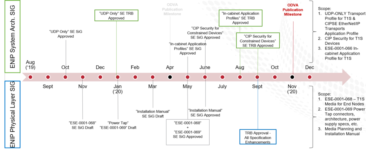
Proposed timeframe
ODVA SIG Proposed Timeline highlights a timeframe of activities to publishing a complete specification for Single-pair Ethernet for Constrained In-Cabinet devices. Definition of the communication protocol and related specification is being defined by the ODVA ENIP System Architecture Special Interest Group, focused on delivering 3 ESEs pronouncing the UDP only Transport profile for T1S (currently to be published April ’20), CIP Security for Constraint In-Cabinet Devices and Constrained In-Cabinet Application profile for T1S.
Definition of the media is conducted in the ENIP Physical Layer SIG, which is focused on delivering 3 ESEs, pronouncing the cable and connector specifications, the SP Tap connectors and grounding specifications and the Media Planning and Installation Manual.
EtherNet/IP media
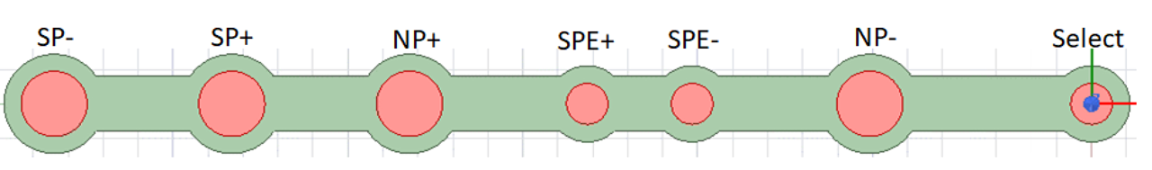
The proposal is for a mixed gauge 7 conductor cable:
- Two conductors for Switched (Control) Power to actuate contactor coils
- Two conductors for Network Power to power device electronics
- Two conductors for SPE Signal Pair for T1S based PLCA Multidrop Ethernet Communication
- One conductor for Select Line for simple sequential network service delivery to discover linear nodal topology.
Wire gauge
- 20AWG wires (19 strands) for NP-, NP+, SP+, SP-
- 24AWG wires (7 strands) for SPE+, SPE-, Select Line
Keying feature
- SPE data pair and Select line conductors will be used as keying feature to minimize chance of wrong connector orientation.
Data pair Impedance
• 100ohm, insulation voltage: 600V.
Media interface
A node connector with 8-pin receptacle interfaces with headers of the constrained devices. The pin header has standard 2.54mm pitch, 0.635mm X 0.635mm square pin.
- 8 pin single row header, 8 pins populated, each pin can carry current greater than 2 Amps
- Connector shall be connected to and make an electrical connection with the media using standard or no tools
- Connector shall break Select line and then establish connections to Select_A and Select_B pins
- Connector may break both SPE+ and SPE- lines and add inline inductors for improved signal integrity.
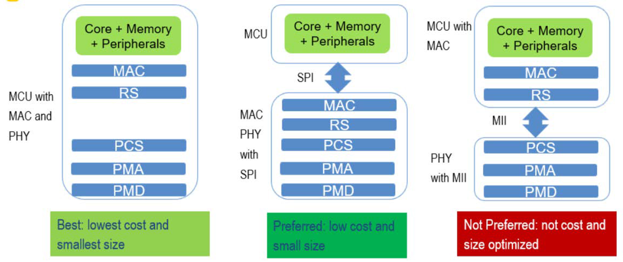
SPE 10BASE-T1S PHY Requirements
Working with different semiconductor vendors for early 10BASE-T1S PHYs, there are three options.
Option 1 is PHY with MII interface, which will require MCU with MAC and RS built in. This is not a preferred option since MCU with MII interface tend to be a lot more expensive than what the constrained in-cabinet device can afford. More than 16 signals need to be routed between PHY and MCU, therefore requires more board space.
Option 2 is PHY with SPI interface with integrated MAC and RS. This will only require a MCU with SPI interface. This is a preferred option since MCU with SPI interface tend to be a lot less expensive and is the target MCU for constrained in-cabinet devices.
Standard organizations are working on standardizing SPI interface for 10BASE-T1S PHY and we have learned from semiconductor vendors that the SPI PHY will be available in 2020.
Option 3 is PHY and MCU integrated on a single chip. This will greatly reduce the overall package size and could potentially offer the lowest cost option. The challenge is to come up with a part that has right mix of processor power, memory footprint and security features, which can be adopted by the mass market.

Design of conductor cable.
SPE 10BASE-T1S media/hardware
Cable Sample
Impedance at 104ohm, Insertion loss of 6.7dB @40MHz for 25 meter
Connector Sample
Insertion loss of 0.1dB@40MHZ return loss of 33dB@40MHz, breaking both SPE+ and SPE-lines, 36nH in-line inductors are built-in.
T1S hardware
Evaluation boards with T1S PHY compliant to IEEE 802.3CG draft 2.1, MII Interface Integrated PLCA functions
System Evaluation Results
- Multiple setups were evaluated to determine the number of nodes that can be supported with T1S hardware, cable and connectors.
- 40 total nodes; master node 0 at the beginning of 25meter cable, node 1 in the middle of the cable, 38 nodes lumped at the end of the 25meter cable
- Conducted BER test with no bit errors.
- Measured eye height at nodes and matched simulation results.
Communication profile & stack

Data transmission communicates from an automation system to a cloud system for further analysis.
Current EtherNet/IP communication does not support constrained device and network requirements. It is proposed to develop a constrained EtherNet/IP communication profile. Note that this differs from the concept of a device profile. The minimum device object model uses the same base objects for constrained EtherNet/IP but minimizes the implementation of the base objects. There are minimized CIP transports over UDP, supporting only UCMM + Class 1.
As part of reducing the overhead in a device, the objects are minimized by limiting the optional features. The Connection Manager is an example. Attributes and services are minimized. The communication methods are minimized. The simplifications still retain the required interoperability.
The application profiles that a device supports are reported via the Application Profiles attribute 25 of the Identity object. Chapter 11 has been proposed for Volume 2, EtherNet/IP Adaptation of CIP to define the EtherNet/IP Transports Application Profile. The new EtherNet/IP Transports Application Profile defines the “Full” and “UDP-Only” transport profiles.
The Full EtherNet/IP transport profile specifies the use of TCP and EtherNet/IP encapsulation sessions for CIP connection management and connected explicit messaging, and UDP transport protocols for implicit message transmission.
The UDP-Only EtherNet/IP transport profile specifies the exclusive use of UDP for the transmission of all CIP messages. This profile, since TCP is no longer required, results in a simplified EtherNet/IP stack.
A new “EtherNet/IP Capability” CPF item is propose, this new CPF item will use the EtherNet/IP Transports application profile data. The EtherNet/IP Capability” CPF item has been added as a valid item to the ListIdentity response. This allows discovery of a constrained device’s EtherNet/IP capability using ListIdentity.
Paired with this is a new EDS entry to describe constrained device’s EtherNet/IP Capability. The following is the define on the new EtherNet/IP Capability” CPF item:
The new EtherNet/IP Transports Application Profile definition allows the combinations of supported features.
The simplification of the communication of an UDP-only device eliminates the TCP connections and the encapsulation sessions and this will reduce the complexity of the communication stack.
Since CIP Security requires both TLS and DTLS, we also propose to add optional support for into the EtherNet/IP adaptation for DTLS-only. Proposed additions to Volume 8 CIP Security will allow devices implementing the UDP-only EtherNet/IP transport application profile, DTLS is used for all CIP communications sent in a CIP Security context.
