

TechnologySeptember 1, 2020
Test bed results: integrating CIP Motion into TSN network
Test bed consists of TSN-capable network bridges, embedded device prototype gateway boards and CIP Motion capable end nodes (PLC and Drive) with prototype firmware supporting TSN. Based on evaluation results, the text bed demonstrated feasibility of integrating EtherNet/IP into networks deploying TSN.
There has been significant activity recently in the market around Time Sensitive Networking (TSN) culminating with both CC-Link IE and Profinet proposing new work items in IEC for TSN extensions to their technologies.
In preparation for work on extending the EtherNet/IP specifications to support TSN, member companies have developed EtherNet/IP TSN test beds. This article will give a report on the lessons learned from the test bed of CIP Motion over TSN.
The test bed consists of TSN-capable network bridges, embedded device prototype gateway boards and CIP Motion capable end nodes (PLC and Drive) with the prototype firmware supporting TSN. The key TSN features supported in this test bed include:
- IEEE 802.1Qbv which specifies a time-aware shaper to schedule traffic. The CIP Motion traffic is inserted into a scheduled part of the network bandwidth.
- IEEE 802.1Qcc which enhances the stream reservation protocol (SRP) and operates at the network control plane
- IEEE 802.1AS which provides peer-to-peer precision time clock synchronization, and is a profile of IEEE 1588 (while CIP Sync uses the default IEEE 1588 profile without peer-to-peer synchronization)
Presented below is an evaluation on the aspects of the TSN adoption method and the performance of TSN adoption for a CIP system. Based on the evaluation results, we demonstrate the feasibility of integrating EtherNet/IP systems into networks deploying TSN. We also propose enhancements and requirements for TSN incorporation into CIP technologies and EtherNet/IP specifications.
Testbed topology and application
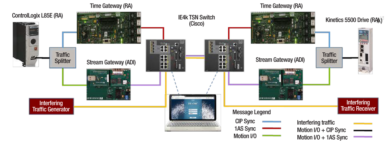
Testbed of CIP Motion over TSN.
As TSN technology mostly impacts critical traffic applications like motion control, we take CIP Motion control as the study case for this testbed. For evaluation of the TSN Scheduling in a converged network, interfering traffic is injected in the system alongside the motion traffic.With reference to test bed terminology, clarifications include the following.
Time Gateway is a prototype implementation that provides the single same time scale for all the components in the system. It is the foundation for scheduling the isochronous type of critical application traffic across the network and application components.
Stream Gateway is a prototype implementation that provides the TSN stream’s scheduling functionality based on Stream Conversion. It can integrate the legacy system traffic into the TSN network and protects critical traffic with scheduled transmission slots.
Traffic Splitter could be a managed switch which is configured to route CIP Sync and CIP Motion messages through different paths. It is used on the present testbed because the Stream Conversion and time translation are separately implemented in the independent Stream Gateway and Time Gateway.
IE4k TSN Switches create a TSN network, which implements the prototype of TSN standards including 802.1AS time synchronization, 802.1Qbv (Enhancements for Scheduled Traffic) and 802.1Qcc (Stream Reservation Protocol (SRP) Enhancements and Performance Improvements).
DE-CNC implements prototype TSN configuration interfaces that are compliant with 802.1Qcc (Stream Reservation Protocol (SRP) Enhancements and Performance Improvements) and can configure IE4k TSN Switches via NETCONF.
Controller and drive represent the user motion control application entities. On the present testbed, only one motion axis is controlled.
Traffic Path Clarifications: Different types of traffic are represented in different colors in figure above. The communication paths for these messages are controlled by the Traffic Splitter and IE4k TSN Switch. The static MAC address table is configured for the path control. STP (Spanning Tree Protocol) is turned off since all static MAC address tables are configured for path control. Since the STP is turned off, communication loops in the system are prevented by access-list control configuration in each IE4k TSN Switch.
Test cases and TSN evaluation
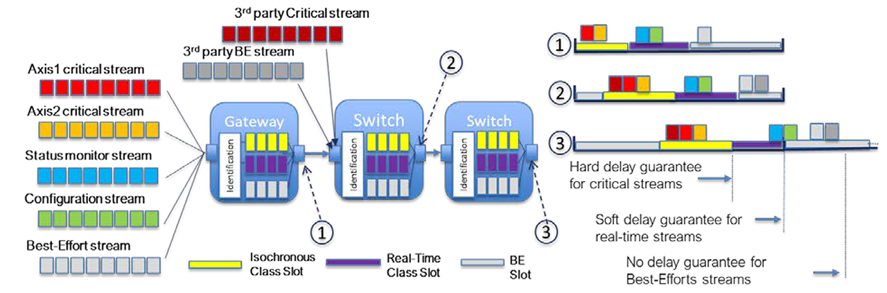
Class-based Scheduling Idea.
We conducted several test cases to evaluate the components’ capability and the whole system’s performance when integrating TSN technologies into CIP Motion control. The detailed test cases and verification results will be presented in this section.
These efforts are advisory to interest holders who are concerned with the TSN technology benefits and adoption key points for automation control applications.
For all the test cases, common configurations of applications and networks include:
- Except as noted, all test cases are run on the “100 Mbits/s” Ethernet for two hours without application connection disconnection.
- In test cases, the CIP Motion I/O messages are assumed to have a conservative maximum frame size of “100 bytes”, although the variant packet size depends on the specific motion connection parameters.
- One CIP Motion axis control is configured with the application cycle of “10 ms”, and the TSN network is configured with the network cycle of “10 ms”. That is to say, the Reduction Ratio is “1″.
- Both CIP Motion controller and TSN network components are configured to start their cycles at the integer times of seconds, i.e. “Top of Second”. By this means, all the components in the system are aligned to the same start point of cycles.
The interfering traffic is generated by a test tool in order to artificially bring the system to the point of CIP Motion system failure, with selected parameters:
- The packet frame size is of “1500 bytes” on the wire
- The messages are transported on UDP, the transport protocol for CIP Motion I/O traffic
- The message is set with DSCP value of “55”, which is same as that of CIP Motion I/O traffic
- The pps (packets per second) is set with value of “8000”. With this setting, the interfering traffic roughly needs the network bandwidth of “96 Mbits/s”.
Test Case 1: CIP Motion Control System over Time Gateway
In this test case, the TSN network of the testbed is enabled with the 802.1AS time synchronization features. Since the legacy CIP Motion application operates CIP Sync protocol (default profile of IEEE1588), the Time Gateway is needed for translating between CIP Sync messages and 802.1AS time synchronization messages.
The performance data is the same as that of the normal CIP Motion application on a standard Ethernet network. And especially in the side work of observing the internal 1PPS (1 Pulse per Second) signals on the both controller and drives, we measure the time synchronization offset with the value around “200 ns”.
This case demonstrates that migration from IEEE 1588v2 default profile to IEEE 802.1AS clock synchronization is viable and can be implemented in a heterogeneous system with both techniques used for different devices.
Test Case 2: CIP Motion Control System over Time Gateway with Interfering Traffic
In this test case, the TSN network of the testbed is configured with Time Gateway as in test case 1 and injected with the interfering traffic in the C2D direction.
The performance degradation (both delay and jitter) validates previous analysis and shows that it is questionable to establish a converged network for both critical applications and interfering traffic with quality of service tags set to the same values.
Test Case 3: CIP Motion System over TSN
In this test case, the TSN network of the testbed is enabled with the features of 802.1AS time synchronization, 802.1Qbv compliant TSN Scheduling and 802.1Qcc compliant TSN Configuration. The TSN Configuration (covering Stream Conversion and TSN Scheduling) is performed in the Stream Gateway and TSN Switch with the stream schedules calculation performed by the DE-CNC.
Stream Conversion is configured in Stream Gateway based on the identification parameters of the application flows of interest and TSN stream identification rules on the bridge networks. Taking CIP Motion I/O traffic for instance, it is communicated on UDP with DSCP of “55” as defined in “3-7.5 Mapping CIP Traffic to DSCP and 802.1D”. So, it is preferred to identify the CIP Motion flows by using tuple-set of {IP address, DSCP}.
In terms of TSN stream identification, it can be identified by the rules as defined in 802.1CB. Among available TSN identification rules, the “Null Stream Identification” rule is simple and implements a passive stream identification function that operates on a tuple-set of {Destination MAC address, VLAN} of stream packets, which is used to identify TSN streams on this testbed.
TSN Scheduling configuration is compliant with 802.1Qcc and needs the user to input application flows requirements together with the system topology.
The system topology can be automatically discovered by LLDP protocol or manually established by users. By using the DE-CNC on this testbed, the IE4k TSN Switch can be automatically discovered but not the Stream Gateway. So, we have to manually add the Stream Gateway.
After the semi-automatic process of establishing system topology, we will input the user application traffic requirements including cycle time, maximum frame size, maximum latency, earliest transmit offset, and latest transmit offset etc. On this testbed, the prototype CIP Motion control has the requirements of Two-Cycle model for Isochronous Motion Control. Specifically, the C2D transfer is expected at beginning of each application cycle and D2C transfer is expected at the half time point of each application cycle.
With user inputs, the DE-CNC calculates the schedules for the TSN streams converted from user application flows and downloads the configurations (e.g. time slot offset and size) into the TSN Switch via NETCONF. In absence of CUC on this testbed, we had to manually configure the Stream Gateway with the schedule and TSN Talker/Listener traffic specification as calculated by the DE- CNC. Although there is no interfering traffic, the performance indicators are worse than that in test case 1. This situation could be caused by:
Factor 1 — Earliest Transmit Offset (application traffic requirement)
EarliestTransmitOffset, according to 46.2.3.5.5, specifies the earliest offset within the Interval at which the Talker is capable of starting transmission of its frames. As part of the TSN-defined Status group, the network will return a specific TimeAwareOffset to the Talker (within the earliest/latest range), which the Talker uses to schedule its transmit.
Ideally, the CIP Motion C2D message is sent at the beginning of the cycle, i.e. earliest Transmit offset is “0 µs”.
However, Stream Gateway needs additional time to process Stream Conversion and Stream Scheduling. So, it will introduce additional delay. This delay was measured as about “300 µs”. The earliest transmit offset should be about “300 µs”.
Factor 2 — Latest Transmit Offset (application traffic requirement)
The variable LatestTransmitOffset , according to 46.2.3.5.6, specifies the latest offset within the Interval at which the Talker is capable of starting transmission of its frames. As part of the Status group, the network will return a specific TimeAwareOffset to the Talker (within the earliest/latest range), which the Talker uses to schedule its transmissions.
Ideally, we could determine the latest Transmit offset by adding earliest Transmit offset with the jitter of “38 µs”. However, the present DE-CNC only allows the minimum of “300 µs” difference between the earliest and latest Transmit offset. So the latest Transmit offset is set to “600 µs”.
Factor 3 – Time slot size (CNC output)
The Latest Transmit Offset and Earliest Transmit Offset that are input by the user will affect the scheduled time slot size calculated by CNC. (Note there are other important factors affecting time slot size, e.g. the application payload size, and the guard band size that is used by CNC to prevent the in-transmission interference traffic). In a preceding hop in the network, the scheduled time slot represents the time span for egressing the packets and in the following hop, there needs a same size of time slot for ingressing the packets.
As all the packets within the time slot are valid for user’s time-sensitive applications, the larger the time slot is, the more addition latency (in the worst case, the packet arriving at the last time point of time slot will still be valid and it will endure the delay equal to time slot size) will be introduced during a switch forwarding process. For instance, in our test, it takes the time slot of “130 µs”. Compared to strict priority transmission where no time slot is used, the most additional latency could be “130 µs”.
Factor 4 — Max Latency (application traffic requirement)
This is an input parameter depending on applications, e.g. C2D messages are required to arrive at drives before half of the cycle. The looser the value is, the easier it is successfully calculate schedules along the communication path for streams. But a loose value also means a big latency.
DE-CNC has the limitation of minimum “500 µs” for this parameter. Since this value is used in the schedule calculation, it will determine the additional latency that is introduced in the form of the time slot size or switch processing time. Its impact on schedule calculation is determined by the scheduling algorithm of CNC.
Factor 5 — Switch Processing Time
When scheduled streams go through a TSN Switch, there is an offset between stream ingress and stream egress,reserved for packet forwarding inside switches. In DE- CNC schedule calculation, it takes a variable conservative value for each IE4000 TSN Switch. Node latency is respectively 80 µs and 20 µs.
Based on these impacting factors, we can roughly calculate the End-to-End latency (by assumption of neglecting the link delay) introduced by TSN Scheduling as: Factor 1 + Factor 2 + Factor 3 + Factor 4 + Factor 5 = 300 µs + 2*130 µs + (in form of Factor 3) + (in form of Factor 3) + 100 µs = 660 µs. Analysis of this delay indicates that at least 360µs is due to known limitations of prototyping equipment such as software-implemented functions like switching that would normally be in hardware and configuration parameters not having full accessibility in software tools. While for non-TSN situation, the End-to-End delay (by assumption of neglecting the link delay) is 94 µs.
The addition latency by TSN Scheduling is 564 µs. This value could explain the experiment observation of additional delay introduced by adoption of TSN Scheduling.
The performance degradation compared to Test Case 1 demonstrates that where there is no interfering traffic (with the same QoS tag values) adding TSN functionality to the network architecture delivers no significant performance benefit to any individual axis and by increasing the mean delay may result in a reduction in the number of axes supported in a given system.
Test Case 4: CIP Motion Control System over TSN with Interfering Traffic
In this test case, the TSN network of the testbed is configured with TSN features as in test case 3 and injected with interfering traffic in C2D direction.
With TSN Scheduling enabled, the critical CIP Motion traffic maintains the same performance even in the condition of interfering traffic. We also tested interfering traffic of “9000” pps (i.e. 108Mbit/s bandwidth). When TSN Scheduling is enabled, CIP Motion traffic still maintains the same performance. While in the case without TSN Scheduling, the communication connection will break down.
With no performance degradation for CIP Motion traffic compared to Test Case 3 we have demonstrated that where there is interfering traffic (with the same QoS tag values) adding TSN functionality to the network architecture can ensure consistent CIP Motion operation in applications where there would have been either performance degradation or system failure using traditional Ethernet technique.
Conclusions: TSN Adoption for CIP
In this section, we will conclude the experiment experience and propose the enhancements or requirements for incorporating the TSN technologies into CIP and EtherNet/IP technology.
Time Gateway is required for adopting TSN technology in the CIP Motion control system that uses CIP Sync for time synchronization. On this testbed, we proved the prototype Time Gateway can achieve a high precision of time synchronization between two endpoints and make the legacy system run over the Time Gateway without performance loss.
Time Gateway needs to handle two time domains of default IEEE1588 and 802.1AS profiles on two ports, involving functions of:
- Time Gateway’s timing port in 802.1AS profile domain needs to support Peer-to-Peer synchronization at layer 2.
- Time Gateway’s timing port in default IEEE1588 profile domain needs to support End-to-End synchronization at layer 3.
- Time Gateway needs to synchronize two time domains to same Grandmaster Clock
The Time Gateway function is preferred to be combined with Stream Gateway function in one implementation entity. Otherwise, the system topology will be complex. The Traffic Splitter has to be used for routing time synchronization messages and control data streams via two separate paths.
Stream conversion & TSN scheduling
Stream Conversion between CIP flows and TSN streams is expected to leverage the “IP address + DSCP” rule. But this method has some issues. This kind of “per-stream” identification is applied for connection with specific peers’ IP address. So, it will require too much work for configuring a complex system with many endpoints.
Since multiple CIP Motion I/O connections’ messages are not sent from the controller in a fixed order, it would be impossible to assign time slots for each motion connection by the “per-stream” identification and scheduling method. If only referring to the DSCP or alike for identifying certain traffic classes and neglecting the specific endpoints’ IP addresses, the “class-based” identification and scheduling mechanism is preferred in the case of multiple CIP Motion axes control. This is in compliance with the traffic classification by DSCP tag in the “3-7.5 Mapping CIP Traffic to DSCP and 802.1D” of EtherNet/IP specification.
The “Class-based Scheduling” idea includes the identification of traffic class. Another point is about the schedules and guaranteed End-to-End delay for each class of traffic. For instance, each egress port of bridges will assign an isochronous slot for the class of critical traffic. Although the sequence of streams are not fixed, the scheduled isochronous slot can ensure the worst-case End-to-End delay guarantee for all streams of this class.
Regarding TSN stream identification, it needs more study about the simplest rule of tuple-set {(multicast) Destination MAC address, VLAN}, considering potential questions:
- Whether there are limitations when applying the stream identification for the “class-based scheduling” function in bridges. If we should use the extended tuple-set of {MAC address, VLAN, extended tags} like the work in 802.1CBdb?
- Whether the Destination MAC address should be multicast or managed. What are the benefits or challenges for different allocation mechanisms of the Destination MAC address?
TSN Scheduling requires a modification to the CIP Motion isochronous application model; it requires the application cycle be synchronized with the isochronous network cycle. Although the “Top of Second” practice can meet this purpose, it has some limitations. The application cycle period has to be a value that is divisible by an integer into 1 second. That is to say, the cycle period can only be “1/n” second, where “n” is an integer.
The “Top of Second” practice is not a standardized rule, which might cause compatibility issues. Actually in “8.6.9 Scheduled traffic state machines” of 802.1Qbv, definitions already exist for the “AdminBaseTime” and related attributes that can be used to set the network cycle’s start point by the state machine.
If taking this approach, all the components need to implement the standard compliant state machines and protocols. Most probably, the applications will be responsible for coordinating the application cycle with the network cycle by the management interfaces.
TSN Configuration and 802.1Qcc
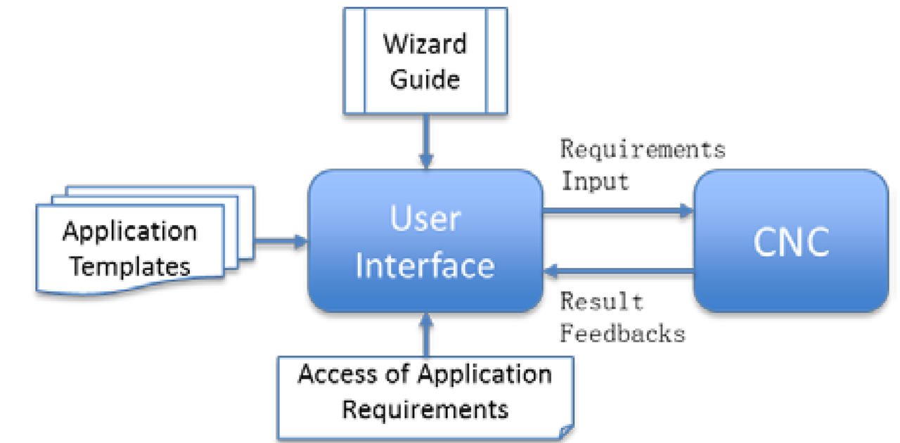
The stream schedule calculation by CNC is an interactive process between applications configuration and CNC calculation. In this process, there are some issues.
The process lacks efficient configuration guidance and most times the user must input multiple different application settings to achieve successful scheduling results by the CNC. It would be desired to design a wizard that can help users to efficiently figure out application requirements either by means of advisory template or parameter tuning suggestions based on CNC feedback.
For now, there are no available interfaces in applications to fetch the required parameters for CNC calculation. Taking the “Earliest Transmit Offset” for instance, we only get the value of about “300 µs” by additional side work. So the next urgent work for application vendors is to define and expose the interfaces for CNC to fetch application requirements.
Future work
This article introduces a testbed that adopts the subset of TSN features (i.e. 802.1Qbv, 802.1Qcc and 802.1AS) into the CIP motion application. It considers existing challenges and suggests a migration path of existing CIP Motion applications using TSN implementations and standards.
In future work, it is desired to improve the testbed by solving known issues and prototyping solutions with TSN enhancements to solve motion application such as Class-based scheduling, 802.1Qbv based application and network cycle start alignment, combined time and stream gateway and native TSN end stations etc.. Based on this evolving testbed, it will be able to verify the TSN migration of EtherNet/IP technology with more comprehensive and solid proofs.