

TechnologyMay 19, 2024
A central network controller for industrial automation
A Centralized Network Controller (CNC) is the centerpiece of a software-defined network (SDN). This article focuses on the CNC's role in production systems, present architectures and key considerations to migrate to these new models and how SW-Defined networks may be applied to ODVA-based industrial automation systems.
Digitization is driving manufacturing innovation. Manufacturers are integrating their own and partner-based digital services and capabilities, creating software defined factories to meet these needs. As well, manufacturers are looking to increase flexibility, improve security and reduce maintenance, separating hardware (HW) from software (SW) and virtualizing key industrial assets.
Applying the power of predictive maintenance, artificial intelligence and digital twins optimizes factory operations and improves product quality at an ever increasing pace, creating Software Defined Factories.
IT has already created an SW-Defined Networking (SDN) model. A software defined production network is needed to provide dynamic, resilient connectivity and security: a SW-defined network for the SW-defined factory.

A Centralized Network Controller (CNC) is the centerpiece of a SW-defined network. This article will focus on the CNC’s role in production systems and present architectures and key considerations to migrate to these new models. We will discuss how SW-Defined networks may be applied to ODVA-based industrial automation systems.
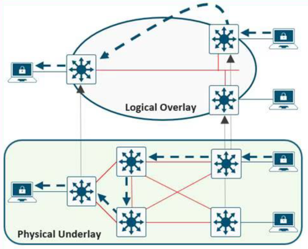
Figure 1. Overlay and Underlay Relationship.
Why centralized network control for industrial networks
A Centralized Network Controller (CNC) provides automated means to deploy, configure, maintain and monitor an industrial network. A CNC is a software application that uses a host of networking protocols to perform these functions, in other words it is the core platform for Software Defined Network.
The key benefits of using a CNC and moving to a Software Defined Networking model include:
- Simplify operations and improve operational effectiveness: the SW-based automation of the CNC can consistently, scaleably and efficiently deploy and maintain industrial networks.
- Deliver Consistent Experiences: A CNC offers a single-pane of glass to deploy, manage and monitor the industrial network usable by both IT and OT personnel.
- Deliver insight in network performance: by gathering telemetry data from the network infrastructure and applying machine learning and analytics, the CNC provides assurance that the network is functioning properly and helps reduce downtime by indicating where issues are and how to resolve them.
- Improve Security and Compliance: A CNC can significantly improve security by automating security policy and provisioning. As well, a CNC can improve consistency and compliance by deploying and analyzing the network configurations on a continuous basis.
All the above are general to networking, specific benefits of an SDN for an industrial network system include:
- VLAN stretching: create extended VLANs to connect devices and applications across an L3- routed network to enable asset virtualization.
- Stretching VLANs also enables the creating of smaller Spanning Tree zones that limits the impact of topology change notifications.
- The SDN model essentially deploys a zones and conduit model specified by industrial security standards (e.g. IEC 62443).
What is a software-defined network
An SDN architecture delivers a centralized, programmable network and consists of the following:
- A controller, the core element of an SDN architecture, that enables centralized management and control, automation, and policy enforcement across physical and virtual network environments
- An Overlay network is a virtual representation of a network
- An Underlay network represents the actual physical devices and connections
An SDN enables the use of virtual networks (overlay networks) running on a physical network (underlay network); the switches, routers and connections, creating alternative topologies to connect and segment devices, such as industrial automation and control devices. Fabric is a term used to refer to the whole overlay/underlay.
This article will outline some of those key protocols that make up the north/southbound APIs, such as LISP, VXLAN, VRF and SGT.
Underlay network
The underlay network is defined by the physical switches, routers and connections that make up the SDN network. All network elements of the underlay must establish IP connectivity via the use of a routing protocol.
In SDN networks, the underlay switches (edge nodes) support the physical connectivity for users and endpoints. However, end-user subnets and endpoints are not part of the underlay network—they are part of the automated overlay network.
Overlay network
An overlay network is created on top of the underlay network through virtualization (virtual networks) described in the following sections. The data plane traffic and control plane signaling are contained within each virtualized network, maintaining isolation among the networks and an independence from the underlay network. Multiple overlay networks can run across the same underlay network through virtualization. In an SDN, the user-defined overlay networks are provisioned as virtual routing and forwarding (VRF) instances that provide separation of routing tables.
An SDN allows for the extension of Layer 2 and Layer 3 connectivity across the overlay through the services provided by LISP. Layer 2 overlay services emulate a LAN segment to transport Layer 2 frames by carrying a subnet over the Layer 3 underlay as shown in Figure 2.
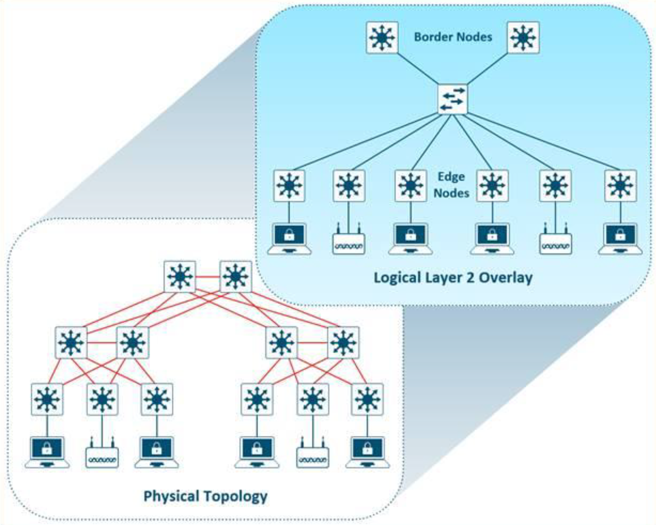
Figure 2. Layer 2 Overlay – Logically Switch Connectivity.
Layer 3 overlays abstract the IP-based connectivity from the physical connectivity. This can allow multiple IP networks to be part of each virtual network. Each Layer 3 overlay, its routing tables, and its associated control planes are completely isolated from each other.
The following diagram shows an example of two subnets that are part of the overlay network. The subnets stretch across physically separated Layer 3 devices–two edge nodes. The RLOC interfaces are the only underlay routable address that are required to establish connectivity between endpoints of the same or different subnet within the same VN.
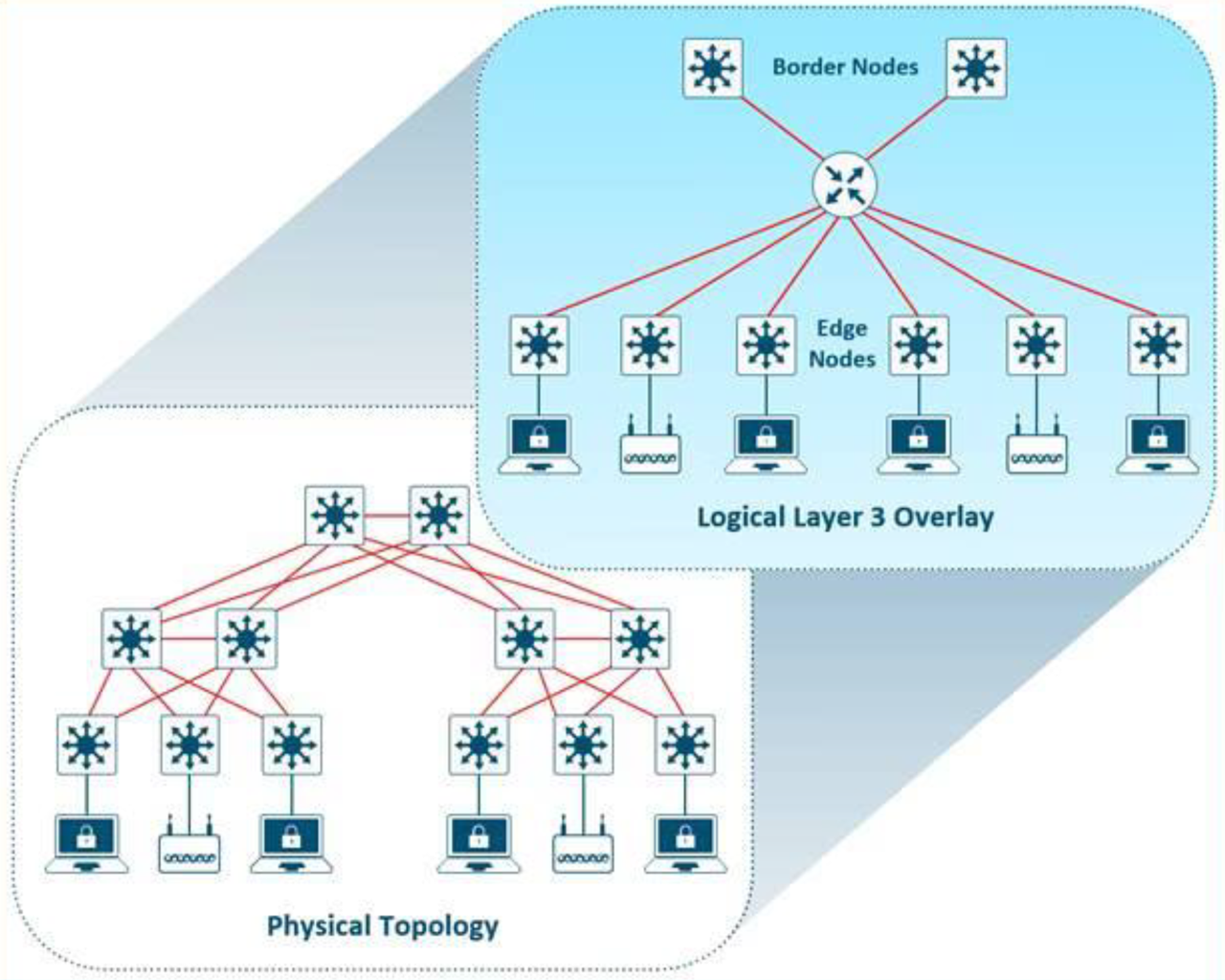
Figure 3. Layer 3 Overlay – Logically Routed Connectivity.
SDN roles
An SDN network consists of 4 key roles. Any network infrastructure device may play multiple roles at any point in time. The four key roles include:
- Control Plane Nodes
- Edge Node
- Intermediary Node
- Border Node
Control plane node
The SDN fabric control plane node manages the tables used to determine where devices are in the network. In this example, the Control Plane node is the LISP Map-Server and Map-Resolver functionality combined on the same node. The control plane node’s database tracks all endpoints in the fabric site and associates the endpoints to fabric nodes, decoupling the endpoint IP address or MAC address from the location (closest router) in the network.
The control plane node enables the following functions:
Host tracking database: The host tracking database (HTDB) is a central repository of Endpoint ID to Routing Locator (EID-to-RLOC) bindings where the RLOC is simply the IP address of the Loopback 0 interface on a fabric node. The HTDB is equivalent to a LISP site, in traditional LISP, which includes what endpoint ID can be and have been registered.
Endpoint identifiers (EID): The endpoint identifier is an address used for numbering or identifying an endpoint device in the network. The SDN solution supports MAC Address, IPv4 Address, and IPv6 addresses as EIDs.
Map-Server: The LISP Map-Server (MS) receives endpoint registrations indicating the associated RLOC and uses this to populate the HTDB.
Map-resolver: The LISP Map-Resolver (MR) responds to queries from fabric devices requesting RLOC mapping information from the HTDB in the form of an EID-to-RLOC binding. This tells the requesting device to which fabric node an endpoint is connected and thus where to direct traffic.
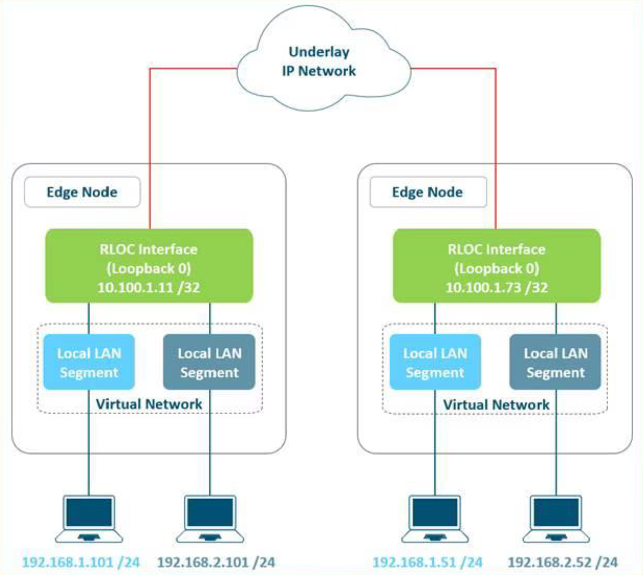
Figure 4. Subnet Stretching – Example..
Edge node
The SDN fabric edge nodes are the equivalent of an access layer switch in a traditional LAN design. The edge node functionality is based on the Ingress and Egress Tunnel Routers (xTR) in LISP. The edge nodes must be implemented using a Layer 3 routed access design. The Edge nodes provide the following fabric functions:
Endpoint registration: Each edge node has a LISP control-plane session to all control plane nodes. After an endpoint is detected by the edge node, it is added to a local database called the EID-table. Once the host is added to this local database, the edge node also issues a LISP map-register message to inform the control plane node of the endpoint so the central HTDB is updated.
Anycast Layer 3 gateway: A common gateway (IP and MAC addresses) is used at every edge node that shares a common EID subnet providing optimal forwarding and mobility across different RLOCs. On edge nodes, the Anycast Layer 3 gateway is instantiated as a Switched Virtual Interface (SVI) with a hard-coded MAC address that is uniform across all edge nodes within a fabric site.
Mapping of user to virtual network: Endpoints are placed into virtual networks by assigning the endpoint to a VLAN associated to an SVI that is forwarding for a VRF. Together, these make up the Layer 2 and Layer 3 LISP VNIs, respectively, which maintain fabric segmentation even at the control plane communication level.
AAA Authenticator: The mapping of endpoints into VLANs can be done statically or dynamically using an Authentication Server. Operating as a Network Access Device (NAD), the edge node is an integral part of the IEEE 802.1X port-based authentication process by collecting authentication credentials from connected devices, relaying the to the Authentication Server, and enforcing the authorization result.
VXLAN encapsulation/de-encapsulation: Packets and frames received from endpoint, either directly connected to an edge node or through it by way of an extended node or access point, are encapsulated in fabric VXLAN and forwarded across the overlay. Traffic is either sent to another edge node or to the border node, depending on the destination.
When fabric encapsulated traffic is received for the endpoint, such as from a border node or from another edge node, it is de-encapsulated and sent to that endpoint. This encapsulation and de-encapsulation of traffic enables the location of an endpoint to change, as the traffic can be encapsulated towards different edge nodes in the network, without the endpoint having to change its address.
Intermediate node
Intermediate nodes are part of the Layer 3 network used for interconnections among the devices operating in a fabric role such as the interconnections between border nodes and edge nodes. These interconnections are created in the Global Routing Table on the devices and are also known as the underlay network. For example, if a three-tier deployment provisions the core switches as the border nodes and the access switches as the edge nodes, the distribution switches are the intermediate nodes.
The number of intermediate nodes is not limited to a single layer of devices. For example, borders nodes may be provisioned on an enterprise edge router resulting in the intermediate nodes being the core and distribution layers as shown in Figure 5.
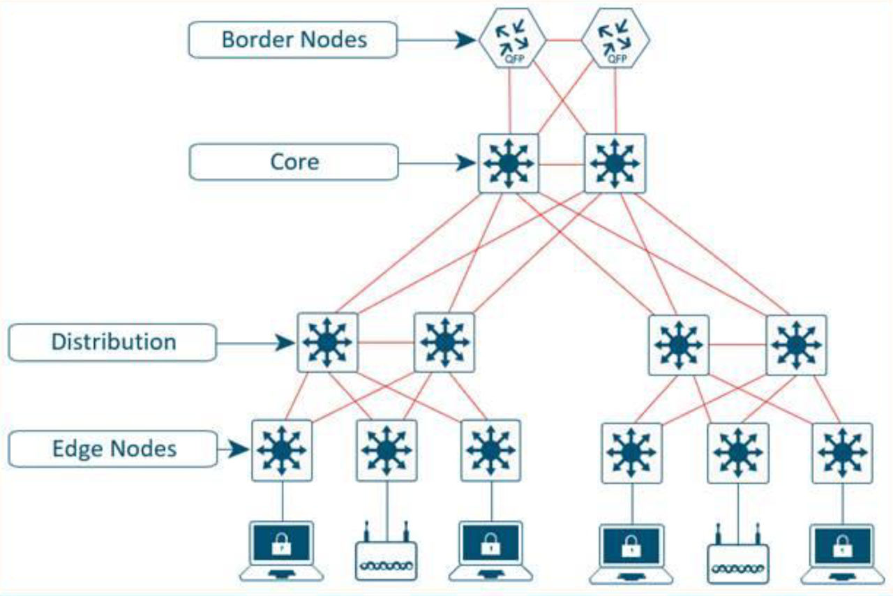
Figure 5. Intermediate Nodes in an SDN – Example..
Intermediate nodes do not have a requirement for VXLAN encapsulation/de-encapsulation, LISP control plane messaging support, or SGT awareness. Their requirement is to provide IP reachability, physical connectivity, and to support the additional MTU requirement to accommodate the larger-sized IP packets encapsulated with fabric VXLAN information. Intermediate nodes simply route and transport IP traffic between the devices operating in fabric roles.
Border node
The fabric border nodes serve as the gateway between the SDN fabric site and the networks external to the fabric. The border node is responsible for network virtualization interworking and SGT propagation from the fabric to the rest of the network.
Border nodes implement the following functions:
Advertisement of EID subnets: BGP (Border Gateway Protocol) is the routing protocol provisioned to advertise the coarse-aggregate endpoint prefix space outside the fabric. This is also necessary so that traffic from outside of the fabric destined for endpoints in the fabric is attracted back to the border nodes.
Fabric site exit point: The external border node is the gateway of last resort for the fabric edge nodes. This is implemented using LISP Proxy Tunnel Router (PxTR) functionality. Also possible is the internal border node which registers known networks (IP subnets) with the fabric control plane node.
Network virtualization extension to the external world: The border node can extend network virtualization from inside the fabric to outside the fabric by using VRF-lite and VRF-aware routing protocols to preserve the segmentation.
Policy mapping: The border node maps SGT information from within the fabric to be appropriately maintained when exiting that fabric. Discussed further in the Micro-segmentation section, when the fabric packet is de-encapsulated at border, SGT information can be propagated using SGT Exchange Protocol (SXP) or by directly mapping SGTs into the Cisco metadata field in a packet using inline tagging.
VXLAN encapsulation/de-encapsulation: Packets and frames received from outside the fabric and destined for an endpoint inside of the fabric are encapsulated in fabric VXLAN by the border node. Packets and frames sourced from inside the fabric and destined outside of the fabric are de-encapsulated by the border node. This is similar to the behavior used by an edge node except, rather than being connected to endpoints, the border node connects a fabric site to a non-fabric network.
SDN components
There are four key technologies, that make up an SDN solution, each performing distinct activities in different network planes of operation: control plane, data plane, policy plane, and management plane.
- Control Plane: Messaging and communication protocol between infrastructure devices in the fabric.
- Data Plane: Encapsulation method used for the data packets.
- Policy Plane: Used for security and segmentation.
- Management Plane: Orchestration, assurance, visibility, and management.
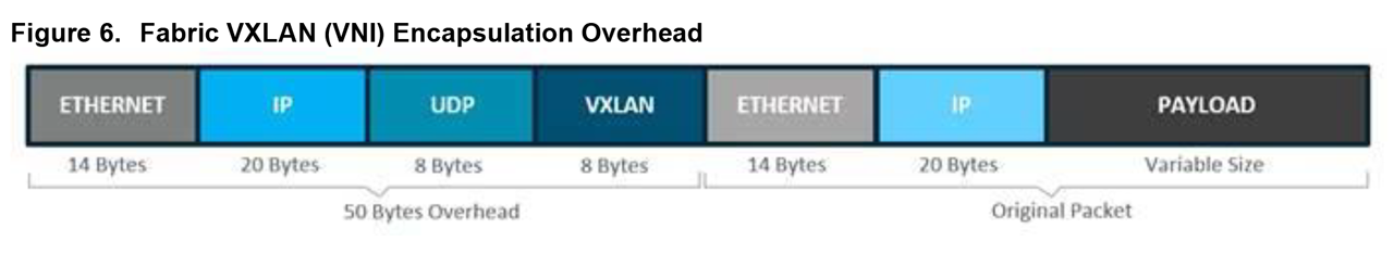
Figure 6. Fabric VXLAN (VNI) Encapsulation Overhead.
Control plane
In many networks, the IP address associated with an endpoint defines both its identity and its location in the network. In these networks, the IP address is used for both network layer identification (who the device is on the network) and as a network layer locator (where the device is at in the network or to which device it is connected). This is commonly referred to as addressing following topology. While an endpoint’s location in the network will change, who this device is and what it can access should not have to change. The Locator/ID Separation Protocol (LISP) allows the separation of identity and location though a mapping relationship of these two namespaces: an endpoint’s identity (EID) in relationship to its routing locator (RLOC).
The LISP control plane messaging protocol is an architecture to communicate and exchange the relationship between these two namespaces. This relationship is called an EID-to-RLOC mapping. This EID and RLOC combination provide all the necessary information for traffic forwarding, even if an endpoint uses an unchanged IP address when appearing in a different network location (associated or mapped behind different RLOCs).
Simultaneously, the decoupling of the endpoint identity from its location allows addresses in the same IP subnetwork to be available behind multiple Layer 3 gateways in disparate network locations (such as multiple wiring closets), versus the one-to-one coupling of IP subnetwork with network gateway in traditional networks. This provides the benefits of a Layer 3 Routed Access network, without the requirement of a subnetwork to only exist in a single part of the industrial network.
Instead of a typical traditional routing-based decision, the SDN devices query the control plane node to determine the routing locator associated with the destination address (EID-to-RLOC mapping) and use that RLOC information as the traffic destination. In case of a failure to resolve the destination routing locator, the traffic is sent to the default fabric border node. The response received from the control plane node is stored in the LISP map-cache, which is merged to the Cisco Express Forwarding (CEF) table and installed in hardware.
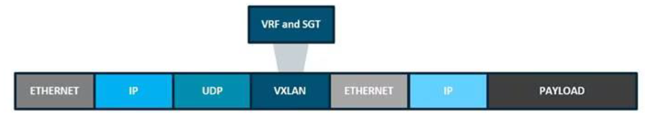
Figure 7. Fabric VXLAN Alternative Forwarding Attributes.
Data plane
VXLAN is an encapsulation technique for data packets. When encapsulation is added to these data packets, a tunnel network is created. Tunneling encapsulates data packets from one protocol inside a different protocol and transports the original data packets, unchanged, across the network. A lower-layer or same-layer protocol (from the OSI model) can be carried through this tunnel creating an overlay. In an SDN, this overlay network is referred to as the fabric.
VXLAN is a MAC-in-IP encapsulation method. It provides a way to carry lower-layer data across the higher Layer 3 infrastructure. Unlike routing protocol tunneling methods, VXLAN preserves the original Ethernet header from the original frame sent from the endpoint. This allows for the creation of an overlay at Layer 2 and at Layer 3 depending on the needs of the original communication. For example, Wireless LAN communication (IEEE 802.11) uses Layer 2 datagram information (MAC Addresses) to make bridging decisions without a direct need for Layer 3 forwarding logic.
SDN networks may also place additional information in the fabric VXLAN header including alternative forwarding attributes that can be used to make policy decisions by identifying each overlay network using a VXLAN network identifier (VNI). Layer 2 overlays are identified with a VLAN to VNI correlation (L2 VNI), and Layer 3 overlays are identified with a VRF to VNI correlation (L3 VNI).
Any encapsulation method is going to create additional MTU (maximum transmission unit) overhead on the original packet. As show in the figure below, VXLAN encapsulation uses a UDP transport. Along with the VXLAN and UDP headers used to encapsulate the original packet, an outer IP and Ethernet header are necessary to forward the packet across the wire. At minimum, these extra headers add 50 bytes of overhead to the original packet.
Policy plane
A policy plane operates by creating logical groupings using two key concepts: Virtual Networks with Virtual Routing/Forwarding (VRFs) and Forwarding and Scalable Groupt Tags (SGTs). The goal is to assign an VRFs and SGTs value to the packet at its ingress point into the SDN network. An access policy elsewhere in the network is then enforced based on this tag information deployed by the CNC or a security policy server.
An SGT is a form of metadata and is a 16-bit value assigned by the CNC or a security policy server in an authorization policy when user, device, or application connects to the network.
The fabric VXLAN encapsulation method is used by both the data plane and policy plane. In the policy plane, the alternative forwarding attributes (the SGT value and VRF values) are encoded into the header and carried across the overlay.
Management plane
The Management plane’s role is to configure and monitor the SDN. The key protocols for managing an SDN include RESTCONF, NETCONF, SNMP and the YANG data models that represent the configuration and management settings for the concepts.
What does this mean for the ODVA ecosystem?
The technologies and concepts for much of this SDN were created for data center virtualization, which is a key aspect of most cloud models. These concepts enable seamless creation and distribution of workloads within the network. The benefits of an SDN include improved operational effectiveness, enhanced security, consistent experience and flexibility. Applied to industrial networks, these concepts may also accelerate the use and integration of cloud and virtualization technologies in production environments.
Key considerations for ODVA’s EtherNet/IP based devices and communication include:
- EtherNet/IP traffic can natively traverse SDN networks. Note that CIP-Sync (Precision Time Protocol) and CIP Motion may not effectively perform as PTP has not been integrated, tested and validated with many SDN deployments.
- Future enhancements for Layer-3 Time Sensitive Network concepts, such as the IETF’s DetNet initiative use aspects of SDN networks, such as VXLAN.
- Enable virtualization of key components in industrial automation networks.
- The SDN concepts allow for standard means to allow applications (such as an Industrial Automation and Control application) to configure the network for application specific requirements.