TechnologyJanuary 13, 2005
GigE Vision: standard route to video over IP

Networked cameras have traditionally handled machine vision pre-processing in situ sending targeted information about the image, rather than the image itself. The advent of Gigabit Ethernet connectivity promises to change the way industry uses networked cameras for machine vision. The order of magnitude bandwidth increase offered by GigE can transfer machine vision processing to a remote PC, in real time.
By George Chamberlain
For want of lower-cost, more flexible alternatives, the industrial vision industry has for years been designing its high-performance applications around short-reach, point-to-point image transfer protocols like Camera Link and LVDS (low-voltage differential signal). Perhaps this explains the buzz in the machine vision world over new application configurations based on standard Gigabit Ethernet connections. In Gigabit Ethernet – GigE – the industry has found an inexpensive transport medium that goes long distances, supports all sorts of networking and processing options and, perhaps most importantly, delivers the high bandwidth needed to stream imaging data from cameras to host PCs in real time. See standards comparison table below.
One measure of the momentum behind GigE has been the initiative by the Automated Imaging Association (AIA) to define GigE Vision, an open standard for seamless interoperation between cameras and applications software from different vendors over GigE. Many machine vision companies including ours have collaborated on the AIA initiative. Our main contribution has been the technical base for the GigE Vision control and stream protocols. Of late, many leading camera companies have rolled out their first GigE camera offerings. Those that haven’t yet done so are scrambling to get GigE product to market.
The GigE interface
The GigE interface sits behind the camera head, inside the camera enclosure. Its main job is to acquire image data, convert it to IP packets, queue it for transfer, and send it over Ethernet. Additionally, it must deliver control signals from the GigE link and other inputs to the camera head, and handle network functions such as boot-up and packet resend.
Two main classes of GigE interfaces are offered: those made from purpose-built hardware, and those derived from a software application on an embedded processor. Fig. 1 summarises the relative benefits of each approach. In general, purpose-built hardware can yield a higher-performance interface capable of processing and transmitting image data at the full, 1Gbps GigE line rate. They easily meet the real-time throughput requirements of most vision applications, including those involving high-resolution cameras with fast frame rates. And they are power efficient, drawing as little as 2W, regardless of how much data they pump out.
| Performance Criteria | GigE Interfaces based on Purpose-Built Hardware | GigE Interfaces based on Embedded Processors |
| Reliability | High: deterministic operation that is easy to validate | Variable: complex validation framework with larger possibility of undiscovered bugs |
| Power Consumption | Very low: virtually constant regardless of sensor sizes and frame rates | Depends on data rates; power consumption increases with data rate |
| Data Throughput | Easily processes data at full GigE line rate of 1Gbps | Depends on processor clock speed: higher speeds yield higher throughputs |
| Latency | Very low and consistent: 200�s to 300�s | Depends on OS: best results with real-time OS |
Fig. 1: Performance trade-offs between different classes of GigE camera interface
The software-implemented GigE interface can achieve deterministic operation at accuracies suitable for many vision applications as long as they use an RTOS (real-time operating system) and a processor with decent clock speeds. However – and this is a key point – the power consumption of these interfaces directly relates to the quantity of image data being processed. Our own analyses indicate that, even with a power-efficient processor, a software interface could draw up to 25W to drive the throughput of a 1600×1200 sensor operating at 50 frames per second. This is just not practical. One way to reduce the power consumption of an embedded processor is to use a co-processor FPGA for some of the protocol processing tasks. This results in a two-chip GigE interface, which is not as efficient as purpose-built hardware. It drives up costs, increases the design footprint, and requires more power, although not as much as an embedded processor on its own.
Performance at the PC
 A key advantage of industrial vision systems with GigE cameras is they don’t require a frame grabber. Instead, data is brought into the PC using a standard, low-cost network interface card/chip (NIC). However, the software drivers supplied by NIC manufacturers use the delay-prone Windows or Linux IP stack to transfer data into memory. Although this doesn’t necessarily matter too much when real-time operation is not critical, the limitation can be circumvented through a more efficient NIC driver. Some of these drivers stream image data directly to user memory at the kernel level of the system in real time, thus bypassing the Windows or Linux IP stack process. Since they don’t engage the IP stack and use intelligent DMA (direct memory access) transfers, these drivers need almost no CPU capacity from the PC. This is important since most applications of them use the CPU to analyse image data as it is streamed into the computer. If the CPU is busy managing data transfer, it is unavailable to the application, making real-time processing impossible.
Drivers often perform another critical function: helping to ensure the recovery of packets dropped by the network. They guarantee data delivery by implementing a sub-millisecond data resend protocol in conjunction with the GigE camera interface ensuring that data is never lost. AIA’s GigE Vision standard supports data resend, but doesn’t define the implementation method or maximum response time, leaving these parameters to be decided entirely by the camera manufacturer. Vision applications that require real-time performance will need to validate that the packet resend capabilities of the chosen camera are sufficient for their application.
Triggering and synchronisation
Many vision applications need to synchronise, trigger, and/or coordinate the operation of cameras with encoders, light sensors, motion detectors, conveyor belts, and other system elements. In the past, this job has fallen to frame grabbers. In systems with GigE cameras without the customary frame grabber, this job has to be done within the camera. Lower-end GigE cameras usually, but not always, include a couple of I/O ports that support basic functions such as external sync. At the other end of the spectrum there are richly featured GigE cameras with I/O capabilities that rival or even exceed those of the most sophisticated frame grabbers. Properties include a flexible signal matrix that allows signals from the I/O, GigE, and camera connectors to be interconnected in hundreds of different ways. Any input can be mapped to any output, activities can be chained, where outputs are fed back as inputs, and I/O signals can be combined in classic Boolean logic operations or manipulated in time.
| Criteria | GigE | 1394b | USB 2.0 | Camera Link |
| Connection Type | Point-to-point or LAN | Peer-to-peer | Master-slave | Point-to-point |
| Bandwidth | < 1000Mbps | < 800Mbps (but only 512Mbps for image data) |
< 480Mbps | Base: 2,380Mbps Med: 4,760Mbps Full: 7,140Mbps |
| Topology | Link | Bus | Bus | Link |
| Cabling | RJ-45, Cat-5 (4 x twisted pair) | 4/6 pin STP | 4 pin STP | MDR-26-pin for Camera Link |
| Camera Interface | External adapter or built in | Built-in | Built-in | Built-in |
| PC Interface | GigE NIC | PCI card | PCI card | PCI Framegrabber |
| Data Transfer Type | Dedicated | Asynchronous / Isochronous | Asynchronous / Isochronous | Dedicated |
| Streaming Video | Continuous | Burst | Burst | Continuous |
| Distance – Max with switches – Max with fibre optics |
< 100 m no limit no limit |
< 4.5 m 72m 200m |
< 5 m 30m – |
< 10 m – 500m |
| Wireless support | Yes | No | No | No |
| Scalability – max # of cameras | Unlimited | 63 | 127 | 1 |
| Multi-Camera Support | Yes | Yes | No | Yes, with multiple frame grabbers |
| Windows driver | Native or proprietary | Native or proprietary | Native | Proprietary |
Comparison of digital transport standards for vision applications
It is possible to build specific relationships between different system elements using a look-up table. Triggers can range from a simple external sync to intricate interoperations. Image capture, for example, can be initiated, interrupted, or aborted by triggers from a single encoder, or by combinations of triggers from encoders, light sensors, and motion detectors.
These higher-end I/O systems also include control circuits such as delayers, re-scalers, and counters. This allows users to fine-tune system operation in numerous different ways. Images can be tagged with timestamps and system actions triggered based on time intervals. Signals can also be delayed by specified time intervals, or have their frequency scaled up or down. Actionable interrupts can be generated from the PC host, and all system elements can be reset simultaneously.
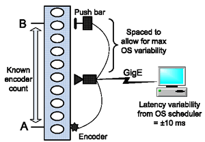
For instance if the software detects a fault after analysing the image of a product, it may have to activate a push arm to remove the product from a conveyor belt. In the past, frame grabbers handled this trigger. With GigE cameras, such triggers can be problematic when the vision application software runs on Windows or Linux: trigger requests may become stalled in OS queues so interrupting real-time signal flow.

Fig. 2: Some GigE cameras can support real-time triggering from a PC application
Figure 2 shows how GigE cameras with full I/O capabilities can bypass this limitation. Each image is time stamped by the in-camera I/O system, and the timestamp is correlated to an encoder count. The encoder count gives the I/O system the precise location of the widget on the conveyor belt. Through system design, the push bar is located far enough away from the camera to accommodate the maximum possible variability from the OS scheduler and any other network equipment. The PC-based application software sends the in-camera I/O system the timestamp of the exact moment the defective widget will pass the push bar, and the push bar is triggered accordingly. This allows applications to precisely time trigger events and synchronise system elements, independent of latency variations in the OS and changes in conveyor speed.
GigE Vision: the three essential elements
For further details, visit www.machinevisiononline.org or contact Jeff Fryman [email protected] at the AIA. |
George Chamberlain is president of Pleora Technologies (www.pleora.com). He is a founding member of the AIA GigE Vision Committee and served as its co-chair until December 2005

