

TechnologyApril 1, 2020
Industrial 5G technology offers potential wireless standard

5G implements technical enhancements over 4G, and is specifically targeting industrial automation. 5G as a technology has already emerged and, even though capabilities are limited, enhancements will continue to be backed by a set of industrial automation players pushing for a common wireless standard.
5G is an upgrade to the cellular system that is not the same as prior generations, where the upgrade focused almost exclusively on improved rates for cell phones. Along with improved rate, enhancements include higher device density, lower latency, increased reliability, and a push for private deployment that all combine to target a wider range of applications.
Expected usage includes Ultra Reliable Low Latency Communication (URLLC) for real time control, enhanced Mobile Broadband (eMBB) for uses including augmented and virtual reality, and enhanced/massive Machine Type Communications (eMTC) for wide-area (usually battery powered) wireless.
Not only did the cellular industry target industrial automation in their IMT-2020 vision, but there is a coordinated effort called 5G-ACIA to rally industrial automation behind 5G and to influence the 5G standards to meet industrial automation use cases and requirements.
The 5G standards from 3GPP are delivered in a series of releases. Earlier releases had already included Ethernet bridging, IP routing, and DSCP-based QoS – valuable features to carry EtherNet/IP traffic.
Release 15 is moving into the market, bringing many of the stated enhancements. Release 16 is in development and goes even further with the addition of TSN capability. Various visions include the replacement of wired switches and the enablement of collaborative mobile manufacturing platforms.
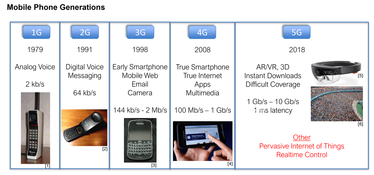
Mobile phone generations. New cell phone generations have emerged about every 10 years.
New 5G generation
New cell phone generations have emerged about every 10 years. The bandwidth of 1G was just adequate for analog voice. The increased 2G bandwidth enabled digital voice and messaging. The increased bandwidth of 3G, along with platform improvements, enabled transmission of pictures, optimized Web pages, and email.
The increase in the platform capability eventually drove the first smart phone. With 4G, we entered the true smartphone era. High resolution screens allowed true internet access by apps. The higher bandwidth enabled the first multimedia streaming. Through all of this, the primary focus was on the improvement of cell phones.
With 5G, cell phone advancements are still important. The large density of cell phones at ballgames, airports, and other public venues presents a challenge to the cellular infrastructure. Users demand high-quality multimedia, regardless of the setting.
In combination with higher rates, 5G brings dramatic latency reduction to enable new capabilities. Mobile interfaces become wearable and immersive. Augmented Reality (AR) and Virtual Reality (VR) depend not only on high rates, they but they must move large amounts of data with low latency, or risk making users nauseated.
Showing larger aspirations, 5G proposes to utilize its low latency for real-time control applications, including those in industrial automation. On another front, 5G is pushing to be the dominant force in low-power wireless devices. While 4G brought features for Low Power Wide Area Network (LPWAN), 5G improves cellular’s competitiveness.
Much of the extended focus is on devices other than traditional cellphones, the so-called Internet of Things (IoT). While each person may carry a single (relatively expensive) cell phone, they may wear multiple (relatively less expensive) devices. They may also utilize a dramatically larger number of devices in their homes, cars, and workplaces, as well as in public settings.
5G feature set
The vision documents for each future generation of mobile telecommunications have been emerging from a single source. Under the United Nations (UN) is the global-scope International Telecommunication Union (ITU). One part of the ITU is the Radio Communication Sector (ITU-R). An initiative of ITU-R, named International Mobile Telecommunications (IMT), develops the vision documents.
5G is the third cellular generation based on these documents. The 3G vision document was completed in 1998, under the name of “IMT-2000”. The 4G vision document was completed in 2008, under the name of “IMT-Advanced”. The 5G vision document was developed between 2015 and 2018, under the name “IMT- 2020”.
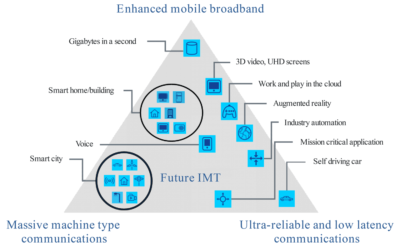
5G triangle from IMT-2020.
5G Triangle
IMT-2020 includes a usage scenario triangle. IMT proposed three broad usage categories on the vertices of the triangle: “Ultra Reliable Low Latency Communication” (URLLC) for real time control, “enhanced Mobile Broadband” (eMBB) for uses including augmented and virtual reality, and “enhanced/massive Machine Type Communications” (eMTC) for wide-area (usually battery powered) wireless.
The three corners of the triangle are roughly related to three aspects of improvement in 5G: increased rate, reduced latency, and LPWAN capability. Within the triangle are more specific usage scenarios. These fall in place by their relationship to the broader categories. Industrial Automation is shown to rely more on high reliability and low latency, and less on high data rate or wide geographic spread.
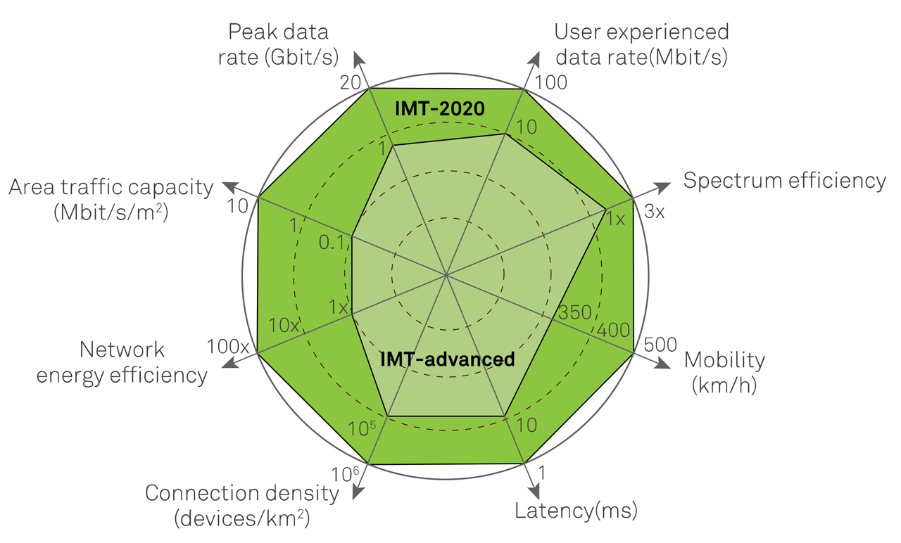
5G spider diagram from IMT-2020.
5G Spider diagram
IMT-2020 also includes spider diagrams for making comparisons which proposes eight technical metrics for improvement over IMT-Advanced (4G). These enhancements combine to target a wide range of usage scenarios.
While there is a 20x increase in the peak data rate, other metrics are worth noting. Low latency of 1 ms (10x improvement) is an enabler for AR/VR applications. It is also an enabler for motion control, but only when combined with high reliability.
Data rates of 100 Mb/s at each automation device would match today’s typical expectation for wired Ethernet. A capacity of 10 Mb/s/m2 may begin to enable wireless in each sensor, not just for limited usage, especially if there can be 1 M devices/km2.
5G Standards development
The Third Generation Partnership Project (3GPP) is the organization where 5G specifications are created and maintained. The specifications are publicly available – free of charge. 3GPP was established in 1998 for the development of 3G cellular.
It was established as an international collaboration of telecommunication standards development organizations (ARIB, ATIS, CCSA, ETSI, TSDSI, TTA, TTC). 3GPP was so successful that they have continued to develop standards for subsequent generations of cellular beyond 3G. Still, the name was preserved.
3GPP is divided into Technical Specification Groups (TSG), each working on a specific aspect of the technology. The Radio Access Networks (RAN) group develops radio specifications from layer 1 through layer 3 for the base station and the user equipment. Core Network and Terminals (CT) group develops the specifications for the layer 3 protocols (session control, mobility, etc.) between the core network nodes, and the interconnection with external networks. Services & System Aspects (SA) develops the specifications for the overall architecture and the services.
Importantly, TC WG3 develops specifications for “interworking” – the connection of the 5G realm to the rest of the world. In 4G/LTE, they created the “Evolved Packet Core” (EPC), which provided an Internet Protocol (IP) packet switching basis for subsequent cellular.
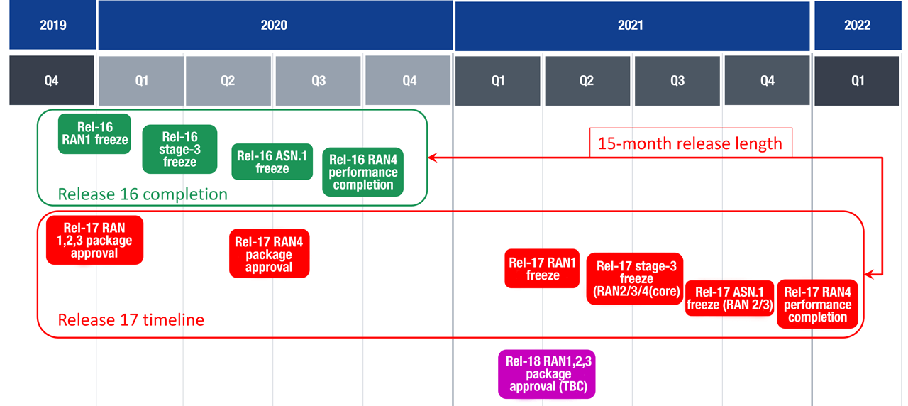
3GPP schedule for Release 17 as of December 2019.
3GPP releases
The 5G standards from 3GPP are delivered in “releases”. A release is a formal specification development process – focused on agreed “work items” (features). A series of releases defines a cellular generation introduction and its enhancement and maintenance. The time to complete a typical release is variable. The releases overlap to reduce the time.
Release 15 is currently moving into the market, bringing many wireless enhancements. It is called 5G NR (New Radio). Two versions are defined. The Non-Standalone (NSA) version leverages the legacy LTE “control plane” to establish connectivity, to roam, and for other related management. The NSA data utilizes the 5G “data plane” for the application traffic. The full native version is Standalone (SA), which uses both control and data plane from 5G. This requires more extensive changes in the core.
Note that the NSA roaming is based on the slower LTE procedures. Control loops operating at 1 ms latency should expect some longer latency where they have to roam. Release 16 is (as of March 2020) in development. It brings the addition of TSN capability. This addition is made to cater to industrial automation use case requirements.
5G-ACIA
Not only did the cellular industry target industrial automation in their IMT-2020 vision, but there is a coordinated effort called 5G-ACIA (5G Alliance for Connected Industries and Automation) with the purpose of rallying industrial automation behind 5G and to influence the 5G standards to meet industrial automation use cases and requirements.
5G-ACIA is a subgroup of ZVEI (a German Electrical and Electronic Manufacturers’ Association). 5G-ACIA was established with the sole purpose of promoting 5G evolution to meet industrial automation needs. It is in part an outgrowth of the German government promotion of Industrie 4.0, which points to 5G as a key enabler in the digitization of industrial automation. Further German government influence led to lightly licensed industrial bandwidth, and German manufacturer commitment to 5G in factories (Volkswagen and Audi in particular).
The membership of 5G-ACIA includes industrial automation leaders as well as telecommunication industry participants at all levels (operators, equipment providers, chip-level providers, etc.). The overlap of the two sets of participants results in the ability for industrial requirements to be brought back into 3GPP. These were brought into the 3GPP releases, along with the key performance indicators, to influence the specification enhancement process.
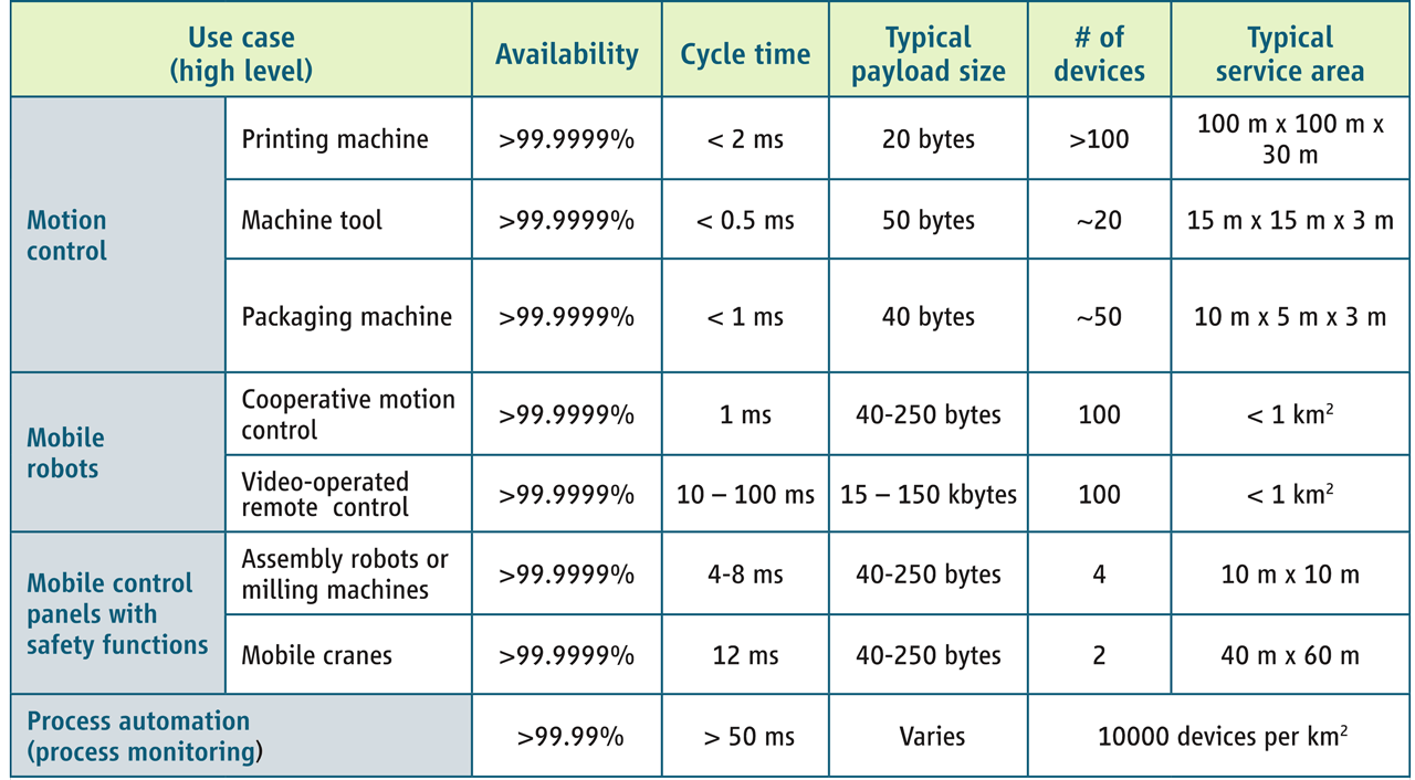
Note that some of the 5G use cases require 99.9999% (Six-Nines) reliability in packet delivery. This is equivalent to wired Ethernet reliability. This represents a Packet Error Ratio (PER) of 1 in 1 million or 10-6. Assuming an average packet length of 1000 bits, this represents a Bit Error Ratio (BER) of 10-9.
System architecture & interworking
At a high level, the 5G System architecture (5GS) includes three main components: the 5G Radio Access Network (5G (R)AN), the 5G Core (5GC), and the User Equipment (UE). The UE is typically a cell phone, but it can be any 5G enabled device. The 5G RAN includes a base station (known in 5G as a “gNodeB”) and the antennas, providing the wireless access point for the User Equipment.
The 5GC includes a Service-Based Architecture (SBA) with functional modules. These include the Access and Mobility Management Function (AMF), controlling access to the system, and facilitating mobility/roaming.
A primary function of 5G is to convey information between the wireless UE and non-5G Data Networks (DN) – e.g., the Internet. This is known in the 5G specifications as “interworking”. The DN is most typically a routed network using Internet Protocol (IP), or an Ethernet network.
The User Plane Function (UPF) acts as a decoupled data plane, forwarding, filtering, and converting packets. The Session Management Function (SMF) acts as the control plane to configure the UPF, creating sessions between UE and DN.
Two important interworking methods are in place: (1) an Internet Protocol (IP) routing method; and (2) an Ethernet bridging method. The two methods include related services, including linkage to outside security. The User Plane Function (UPF) plays a key role in data movement.
The IP routing includes use of IPv4 or IPv6 and DSCP-based QoS, with the SMF acting as DHCP client/server, as well as linkage to RADIUS/AAA and other security services.
The Ethernet bridging utilizes the User Plane Function (UPF) to strip and add Ethernet headers on ingress and egress, stores Media Access Control (MAC) addresses for bridging decisions, and acts as an Address Resolution Protocol (ARP) proxy.
Note that the UE may also include routing or bridging function internally. This allows compliant design of an adapter to a wired subnet or the creation of a fully embedded wireless solution. These 5G interworking specifications are valuable features to carry EtherNet/IP traffic. Early testing by Rockwell Automation indicates that unmodified EtherNet/IP protocols can run over 5G.
Spectrum
5G spectrum is only roughly harmonized on a worldwide basis. Most of the spectrum is currently licensed (under control of the operators). Unlicensed and flexibly licensed bands exist and are growing in availability. The US promotes 3.5-3.7 GHz (CBRS band) with a license database to reserve exclusive use of channels within a limited geography. Germany introduced 3.7-3.8 GHz with company licensing. Unlicensed spectrum generally requires Listen Before Talk (LBT), impacting determinism.
In Release 15, 3GPP specified two broad frequency bands: FR1 (410 MHz to 7.125 GHz) and FR2 (24.5 GHz to 52.6 GHz). Technical differences are specified for radios that are designed for each band.
The cellular industry created a further logical division into three functionally different layers: (1) The “low-band”, below 1 GHz, applying only Frequency Division Duplexing (FDD), and known as the “coverage layer” due to better propagation characteristics; (2) The “high-band”, above 24 GHz, applying only Time Division Duplexing (TDD), and known as the “Super Data Layer” due to high data rates; and (3) the “mid-band”, between 1 and 6 GHz, applying mostly TDD, and known as the “Coverage/Capacity Layer” as it is a compromise between the other two bands.
The low-band services provide for remote rural coverage as well as LPWAN. Standard cell phone usage falls into the mid-band. Applications demanding the highest rates and lowest latency will utilize the high band. Coverage is then more difficult due to the poor propagation characteristics of the mmWave signals (blocked by most everything, including windows). On the other hand, the poor propagation facilitates channel reuse by blocking the signal at a facility boundary.
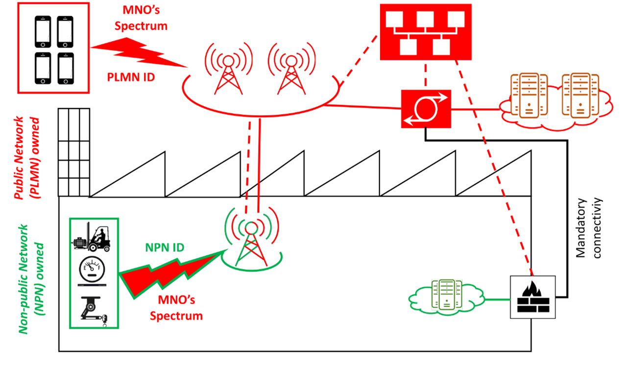
System diagram for standalone Non-Public Networks (NPN).
Non-Public Networks (NPN)
New deployment models are emerging with 5G. Previously, cellular systems were totally controlled by the Mobile Network Operators (MNOs). End users could develop the UE, adding Subscriber Interface Modules (SIMs) to bring them into a Public system. 5G brings options for Non-Public Networks (NPN) to the end users.
Several NPN models exist, starting with a full stand-alone NPN, where the end user owns all the equipment, the control plane or 5G core (5GC), the data plane (UPF), the Radio Access Network (RAN), and the private spectrum. In hybrid models, only some portions are private.
Based on market studies, cellular participants estimate that NPN deployment will lead to 3x increase in the number of base stations that are deployed. This is high motivation for equipment vendors. The bulk of the estimate is for industrial automation deployment.
Local equipment can improve URLLC performance, closing the loop closer to the equipment. The easy containment and high rates of mmWave may also be of benefit.
Challenges exist in achieving the NPN vision. The traditional cellular system is comprised of a large set of specialized equipment. The size and cost must be reduced and ease-of-use improved dramatically to enable practical use by the average industrial automation site. One positive trend is the emergence of “small cells”. This brings more bandwidth to smaller areas. The equipment must then be small and economical.
Another challenge is that private spectrum is difficult to procure. Since operators may benefit by NPN participation through sub-licensing spectrum, selling equipment, or providing installation/management services, this cooperation may be key to providing adequate bandwidth and avoiding interference between sites. 5G’s “slicing” technology allows operators to partition their 5G network into virtual networks (both the RAN and the 5GC), coordinating between industrial automation sites, and providing Service Level Agreements (SLAs) to each site.
Frame structure
5G communication is based on a standard frame structure. 5G repeats a fixed 10 ms radio “frame”. The frame contains 10 fixed “subframes” of 1 ms each. This fixed frame structure provides the basic timing, matching the legacy LTE fixed frame structure.
Within a subframe, there are a variable number of “slots”. The slot length, and number of slots in a subframe depend on the “subcarrier spacing” (SCS). Small SCS (i.e., 15 kHz) has less bandwidth and is extended in time to increase the energy, large SCS (i.e., 120 kHz) has more bandwidth and the slot can be shorter in time (125 us).
Each carrier may be modulated using Quadrature Amplitude Modulation to carry up to 256-QAM (8 bits per symbol). A variable number of subcarriers (up to a maximum bandwidth) are modulated simultaneously to form a symbol using Orthogonal Frequency Division Multiplexing (OFDM). A slot (usually) consists of 14 symbols.
Considering the frame in frequency and time, it composes a resource grid. Blocks of user data can be packed into the grid by a scheduler using Orthogonal Frequency Division Multiple Access (OFDMA).
The 5G frame can mix upstream and downstream traffic within slots. Each symbol may be assigned as uplink, downlink, or flexible, following a set of predefined slot formats. Some formats have more downstream symbols, some more upstream, and some alternate for sub-slot turnaround and reduced latencies.
Note that the same basic frame structure can be used for all purposes. While this section described TDD, where transmission and reception occur on a single channel, the same basic frame structure applies to FDD, where there is continuous transmission and reception on separate channels. The same frame structure also supports unlicensed band usage, where the start of a slot is sacrificed for the Listen Before Talk (LBT) procedure. There may also be “mini-slots”, with a small number of symbols and a flexible start time. This allows low latency for URLLC transmission.
Fading
Wireless channels are not constant, but experience impairments. The fluctuation of the signal strength at the receiver is known as “fading”.
Fading can be broken down into types. Some classifications consider “path loss” as a type of “large scale fading” based on transmit distance, which can be compensated by increased signal. Another type is “small scale fading”, where the signal fluctuates rapidly over short time and distance – making it hard to compensate. Changes may be induced not just by motion of the transmitter and receiver, but by changes in the surrounding environment (e.g., moving metallic objects).
Statistical models are developed for the fading channels. Radios can be designed against the statistical models, but the real channel may vary in dynamic ways. Rapid channel measurement can enable compensation. Depending on relative motion, the channel can only be assumed to meet the measurement for a fixed time period (the “coherence time”), then it must be re-measured.
Some impairments such as “fast fading” can be compensated by retransmission, as the fading only lasts for a short period. This and related techniques can add unpredictable latency, contrary to URLLC goals. Fading can change faster than adaptations are made. The result is additional retransmissions to compensate for the unreliable channel, leading to unpredictable latency.
Channel hardening
Considering a channel between a transmitter and a receiver, the gain may vary (in time and frequency) due to fading. Decreasing the variation is known as “channel hardening”. If the variation is adequately reduced, the channel behaves deterministically – as if there is no fading.
Channel hardening can be achieved by applying “spatial diversity”. If the number of antennas is increased between the transmitter and the receiver, each with a slightly different path with regard to the fading, by combining the antenna signals we approach an average channel gain (over a large enough period, we can average out the fading) for the instantaneous value.
There are now several practical implications. The signal is improved across both time and frequency. Latency is lower and transmissions can be scheduled.
An additional benefit is the ability to utilize (only) uplink pilots for channel estimation. By utilizing TDD, reciprocity can be applied. The upstream and downstream channel can be estimated to be the same. A single upstream pilot from a UE arrives to multiple antennas at a base station. The large number of antennas is used for channel hardening. The base station can compensate for the channel in both directions, by combining the multiple receive signals and by manipulating the multiple transmit signals.
Massive MIMO
“MIMO” (Multiple In Multiple Out) is a technique that combines multiple antennas (in the same channel) for various improvements. Much like some directional antennas, “beamforming” uses multiple antennas with the same data stream to increase the gain and to steer the signal, improving distance and decreasing some interference. Spatial multiplexing sends different data streams from the multiple antennas to increase throughput.
5G brings “massive” to MIMO, deploying a very large number of antennas attached to the base station (ideally 100’s). This can bring benefits to even unmodified UE. Some argue that this is the single improvement that makes 5G worthwhile.
In an example MIMO system, the large antenna array targets multiple users. The large number of transmit and receive chains are coordinated at a system level. An 8 x 8 array (64 dual-polarized antennas) is typical. The array transmission and reception can be configured to form multi-antenna beams to multiple users. The benefits include full cell capacity for each user, high reliability, and low latency – based on channel hardening and rapid channel estimation.
Coordinated multi-point
The massive MIMO technique can be extended by spreading the antennas across a site. This technique is known as Coordinated Multi-Point (CoMP), or as “distributed MIMO”. CoMP bring the same general improvements – an increase in the capacity within the site and/or low latency with increased reliability. It can also further harden the channel by increasing the antenna diversity.
As explained by Qualcomm, blockage and reflections from fast moving metal objects within industrial automation can cause sudden drops in signal strength. It is implied that (CoMP) can maintain reliable operation and low latency under such conditions. Note that the distributed antennas must be tightly coordinated. A CoMP server tunes the signals from each antenna set. Note that CoMP is not a new technique. It was applied to LTE in 2009.
Low power wireless
5G promises improvements in low power wireless. LTE-M, NB-IoT and EC-GSM-IoT are specified. While these low power radios are not new, there have been enhancements. It has been shown that all three technologies can achieve battery life longer than 10 years with two AA batteries totaling 5 Wh. This requires a daily report consisting of a 200 byte message at data rates < 1 kb/s and latency approaching 10 seconds, with 164 dB MCL.
The Maximum Coupling Loss (MCL) is a channel-independent measure to describe the expected wireless system coverage. While nodes could transmit > 10 km under ideal conditions, citywide coverage is a primary target, with interstation distance in the range of 250 m to 2 km. Deeply embedded nodes are the challenge, where in parking garages for example, we may lose 50 dB through concrete walls. In order to work under these lossy conditions, redundant transmissions are applied – reducing battery life.
Release 15 continued adding improvements to help meet increased performance requirements relative to LTE (4G). The number of messages needed to participate in the network were reduced. Small cells, located closer to UE, allowed the reduction of transmit power. A small Wake Up Signal (WUS) was introduced. A battery-efficient security technique (BEST) was added – in-part as a confidence builder for IoT proliferation.
Active transmission uses the most power. LTE-M and NB-IoT radios have 164 dB MCL and transmit at 14, 20, or 23 dBm. Each halving of the distance can gain back 6 dB. Mesh techniques are also considered for better coverage and to reduce distances. “Generalized” beamforming is another technique that can be applied. Each doubling of the antennas can add 3 dB of gain. In one study, 200 antennas demonstrated 28 dBi. Reductions of transmit signal power do not translate in a linear fashion, but chipsets are improving each generation to be more efficient by utilizing more efficient power amplifiers. 5G IoT radios are under continuous improvement, driven by a huge technical community.
5G industry vision
5G is arriving with one of the largest marketing pushes ever. In virtually every manufacturing company of any size, someone is assigned to develop their 5G vision. While wireless has been available for a long time, and applied in numerous industrial automation applications, it has not become ubiquitous. 5G may bring some new vision, or at least may deliver better capabilities to meet unsatisfied visions.
As stated by the 3GPP Chair from Nokia, Release 16 pursues Ethernet replacement in the factory. This includes the addition of TSN.
One vision is the replacement of wired switches with 5G wireless. Supervisory control may be a good candidate due to the lower rates to interlock and coordinate across equipment, and the larger distances of cable runs. This includes the IT/OT boundary and MES connections.
Another vision is the enablement of lean collaborative mobile manufacturing systems. Besides replacing Ethernet between fixed machines/cells/lines (which has benefit), wireless untethers the equipment. While the mobile equipment may just move materials (AGVs), mobile platforms can also carry parts-in-process to fixed application platforms. Each part can be different. Process reconfiguration can be rapid.
Conclusions
5G will implement a wide range of technical enhancements over 4G. These enhancements improve on prior wireless solutions and may open new market areas including industrial automation.
5G has already emerged; capabilities are limited, but enhancement will continue. For the first time, we have a substantial set of industrial automation players pushing for a common wireless standard – 5G.
Since 3G, the 3GPP standards have included: packet switched Internet Protocol, Ethernet connectivity, and quality of service matching EtherNet/IP needs. Paradigm shifts may be either an opportunity or a threat.