

TechnologyMay 18, 2025
Ecosystem expansion using EtherNet/IP In-cabinet solution
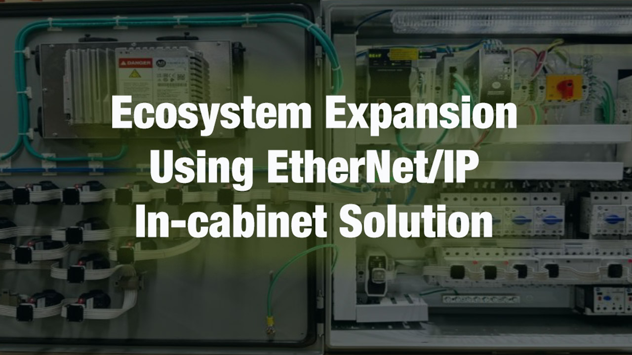
The EtherNet/IP In-cabinet solution brings wire reduction and information enablement to field level devices like simple industrial components, pushbuttons & contactors. The single cable solution provides all appropriate electrical connections to each component to operate without the need to connect additional control wiring.
EtherNet/IP In-cabinet is intended to replace the hardwiring between devices with a single composite media that provides both power and communication. This innovative approach simplifies installation, reduces engineering time and leverages the intelligence in the devices to provide greater information for maintenance and process optimization.
In this article, we highlight the transformative impact of the SPE/T1S implementation, as defined by ODVA’s released specification. We will explore the expansion of the EtherNet/IP In-cabinet ecosystem and discuss strategies to overcome barriers to technology adoption.
This includes sharing knowledge on the EMC performance of flat ribbon cables, expanding application use cases through integration with CIP Safety, futureproofing with compatibility to upcoming IEEE standards, and advancements in flat media and connector development in IEC standards.

What is EtherNet/IP In-cabinet?
To fully appreciate the value of the EtherNet/IP In-cabinet solution, one must understand where we’re coming from or how this solution compares to methods that are currently being used and have been for over a century. The longstanding methodology of In-cabinet wiring in industrial automation is now on the verge of transformation.
Control wiring for In-cabinet I/O devices like push buttons, indicators, relays and motor starters is crucial in industrial automation. It ensures the interface between physical components and logical control, traditionally hardwired in point-to-point configurations. These devices are essential in electrical control systems for machine control, serving as inputs and outputs for traditional PLC control.
When estimating traditional wiring time, 6 minutes per wire (3 minutes per termination) is a useful guide. Though this may not seem significant for a single wire, control systems often have several hundred wires, depending on their size and complexity. A simple non-reversing motor starter with local panel control, like a Hand/Off/Auto (HOA) selector with a 3-wire start/stop function, requires 13 physical wire terminations.
Traditional wiring methods consume time. It is important to understand time and higher costs can be realized in added engineering creating more complex electrical control wiring diagrams, further costs in ‘testing’ can be realized as all control panels undergo point-to-point wiring to validate and ensure the panel performs as intended.
The EtherNet/IP In-cabinet Solution will replace traditional hardwiring between devices with a single composite network cable that includes both power and communication. The system achieves a reduction in device complexity by utilizing a multi-drop bus topology, reducing device interface complexity and the average number of interfaces per device.
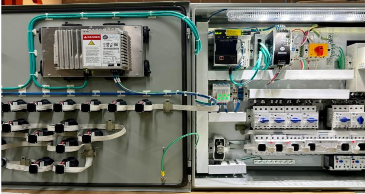
Installed EtherNet/IP In-cabinet solution

Conventional panel.
The Value of EtherNet/IP In-cabinet Solution
Implementation of EtherNet/IP In-cabinet solution.
This shift from traditional hardwiring to a network-based solution offers unparalleled benefits. In a recent time study initiative, building two like panels, one traditional the other EtherNet/IP In-cabinet Solution has shown significant savings on average are achievable; 80% reduction in wiring time, a 30% reduction in project engineering time and 50% reduction in testing time. Further savings can be realized in reduction of capital costs and panel sizes.
The EtherNet/IP In-cabinet solution is defined in CIP Volume 2 as the In-cabinet usage profile. The specifications include physical layer requirements as well as implementation of UDP-only transport profile and various required objects/services. This premier integration In-cabinet solution allows the PLC controller direct data access using EtherNet/IP connectivity to field level devices such as simple push buttons, contactors, and motor starters.
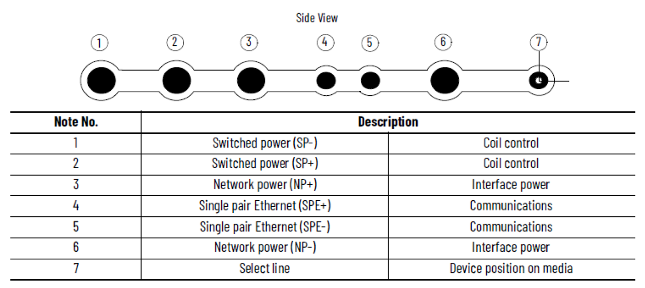
Side View and Description of EtherNet/IP In-cabinet Cable
By providing direct data access, vital predictive maintenance data such as the number of operations and number of hours can be obtained for each device. The specifications also defined a constrained security profile for In-cabinet devices, making it possible to enable CIP security for field level devices.
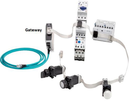
An EtherNet/IP gateway, shown in the figure above, connects the devices on the In-cabinet bus to a standard EtherNet/IP network to allow communication between a controller and the devices.
The Gateway has integrated First Power Tap, and supplies both NP (Network Power) and SP (Switched Power) to a multidrop bus system. Network Power supplies communication electronics with a 4 amps capacity whereas Switched Power is used for switching larger loads such as contactor coils with 4 amps capacity with boosted ampacity to 8 amps. This is to account for the initial inrush current when the loads are switched on.
The 7-conductor flat cable passes power and signal to and between communication interface devices in a multi-drop In-cabinet network. All the nodes are connected to a single cable.
Various EtherNet/IP In-cabinet connectors, their functions and intended usages are shown in Table 1. The detailed specifications are included in ODVA specification Volume 2: EtherNet/IP Adaptation of CIP, Chapter 8: Physical Layer. The connectors allow quick field termination with standard tools.
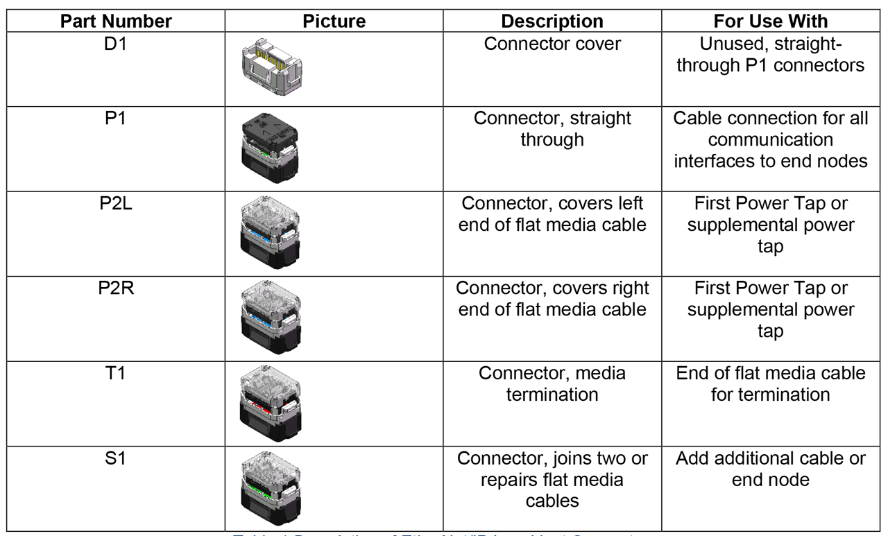
Table 1: Description of EtherNet/IP In-cabinet Connectors.
EtherNet/IP In-cabinet End Node Devices
ODVA specifies 25 meters for In-cabinet network cable length and a maximum node count of 40. Each end node requires a 10BASE-T1S transceiver operating in multidrop mode. Examples of end node devices include three position selector switch, momentary pushbutton, pilot light, non-reversing motor starter and reversing contactor device.
EtherNet/IP In-cabinet Panel Bi-direction Select Line
One of the key differentiating features for In-cabinet technology is its use of a bidirectional select line. A single conductor that runs through In-cabinet media facilitates sequential command delivery. Application of Plug Connectors to the bus cable, severs the select line into separate segments. The two segments adjacent to each node are brought into the node on Jack Connector pins, SEL_A and SEL_B as shown above. A signal chain is formed by the segments, the attached Select Line Circuits, and the MCUs. On initial power up, the “Select A” and “Select B” pins on all nodes are configured to be input pins. After a first message is detected on one of the Select pins, the other Select pin is configured to be an output pin. System wide sequential commands are delivered for actual topology discovery, system commissioning and device replacement operations.
Select Line Enables Flexible Cable Routing Direction
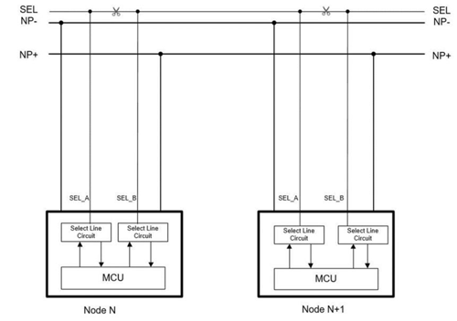
Interconnection diagram for Select Line
The Select line allows for bi-directional communication and flat media can be routed left to right or right to the left. Panel builders can minimize excess cable length to make cable routing neat, clean and easy to track down devices by visually following the flat cable.
A significant advantage is the ability to change the panel component layout and routing of the cable without impact to the PLC program. An example on the following page shows flexible cable routing for an In-cabinet network of 23 devices. Cable for nodes 0 to 3 and nodes 10 to 20 is routed from left to right, while cable for nodes 4 to 9 and nodes 21 to 22 is routed from right to left.
Select Line Enables In-cabinet Commissioning
The In-cabinet Commissioning Object works with the Select Line Link Object and the In-cabinet Actual Topology Object to facilitate node commissioning (configuration of T1S PHY settings, and TCP/IP Interface Object) for EtherNet/IP In-cabinet network.
In-cabinet Commissioning Object is typically implemented in the Gateway or First Power Tap, and it must be the first (leftmost or rightmost) node on the In-cabinet network.
Various addressing schemes, using the last octet of the IP address, e.g., can be implemented:
- Sequential IP addressing based on topology location of the devices on the cable
- Next Available IP addressing based on “next available node address” for each newly added device
- Manual IP addressing to match the address in the Reference Topology
When a user adds a new device to a fully commissioned In-cabinet network, he or she can assign an unused IP address to the new device and keep the same IP address and configuration for all the original devices. This will greatly minimize the impact on other components/applications in the system. After the new device is added to the controller I/O tree and update to Gateway reference topology is completed, the new controller program can be downloaded to establish I/O connection to the new device as well as all the original end node devices.
Select Line Enables Auto Device Replacement
In the event of an end-node failure, a new device can be installed at the same location to automatically replace the old device.
This process would be initiated when the 24V DC control power to the system is switched off, the failed device is removed and a new device is installed, re-connected to media, and 24VDC control power is reapplied. This triggers the Gateway to initiate the Discover Topology Service to determine the actual topology. When the reference topology and new actual topology match, the Gateway configures the end node with the IP address of the replaced node. The connected system PLC will respond and download the configuration parameters to the new devices and re-establish all IO connections.
In-cabinet Panel Enables Data and Predictive Maintenance
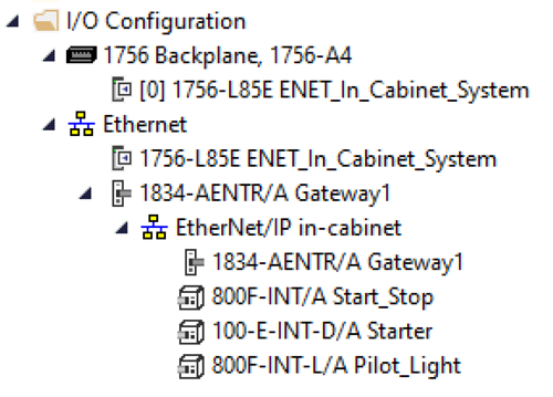 EtherNet/IP In-cabinet technology enables ethernet connectivity all the way to field level devices like pushbuttons and contactors. Adding In-cabinet devices to a controller configuration can potentially be achieved with similar user experience as standard EtherNet/IP devices.
Using Rockwell Automation’s Logix Designer tool, the figure above shows an example of an In-cabinet network. For the example implementation, to add an In-cabinet network, the first step is to right-click Ethernet network icon and add a Gateway device to the I/O tree. After the Gateway is successfully added to the controller I/O tree, EtherNet/IP In-cabinet network will be displayed under the Gateway. Any In-cabinet network device can be added with a few mouse clicks.
The number of operations, number of operating hours, fault value, blink rate, dimming levels, etc. are all available from controller tags. EtherNet/IP In-cabinet technology enables controller direct access to data from field level devices like push buttons and contactors. Predictive maintenance for field level devices can be made possible to minimize downtime and improve productivity for end users. For example, predictive maintenance for contactors can be calculated based on the number of operations and/or the number of hours. An end user can also set an alarm and get notified when the non-reversing starter reaches 10% remaining life and replace the starter before it fails.
EtherNet/IP In-cabinet Supports Security
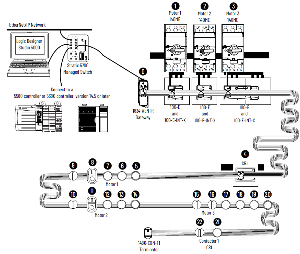
Example to show flexible cable routing for In-cabinet network.
Table 11-3.2 in Volume 2: EtherNet/IP Adaptation of CIP lists all the requirements to support the In-cabinet Usage application profile and constrained CIP Security Profile is listed as an optional requirement. Security for In-cabinet device is based on the Resource-Constrained CIP Security Profile, defined in Volume 8, CIP Security. Resource-Constrained CIP Security Profile requires implementation of DTLS on UDP, CIP security object, EtherNet/IP Security object, PSK-based cipher suites, etc. Support for CIP security down to field level devices is one of the competitive advantages for In-cabinet technology. Configuration of Security Policy of In-cabinet Devices can be made easy and straightforward.
Noise Immunity
The EtherNet/IP In-cabinet system is capable of meeting rigorous industrial product standards: EN IEC 61010-2-201, EN IEC 60947-4-1, EN IEC 60947-5-1, EN IEC 60947-1, IEC 61326-1. Table 2 is a summary of the immunity test levels and acceptance criteria.
IEEE SPE Standards Alignment
EtherNet/IP operates over numerous IEEE Ethernet Physical Layer (PHY) standards. The common property is that the Ethernet frame format remains the same. Upper layers are then supported with little or no modification. IEEE Ethernet PHY standards for multipair copper and fiber variants are the most well- known. Industrial Ethernet for multipair 100 m copper media has evolved from 10 Mb/s over two pairs to 1000 Mb/s over four pairs. Ethernet evolution continues toward higher rate and complexity on this “multipair Ethernet branch”.
Development of a Single Pair Ethernet (SPE) branch started in 2014 when IEEE members affiliated with numerous automotive vehicle companies (BMW, GM, Volkswagen, Daimler, Peugeot, Mazda, Opel, Toyota, Nissan, Jaguar, Hyundai, Renault, Volvo, Ford, Honda, and others) began standardizing new PHYs that were suited to the creation of an all-Ethernet car. The primary goal was to reduce the increasing wiring harness complexity and weight by replacing discrete wires and up to eight different networks that ran in parallel within the wiring harness. An additional goal was to enable value-added features by standardizing on Ethernet to enable free flow of information across the sub-systems that were previously linked by incompatible networks.
IEEE members affiliated with industrial automation companies (Rockwell Automation, Endress+Hauser, Pepperl+Fuchs, Siemens, HARTING, Schneider Electric, ABB, VEGA, Stahl, Turck, Hirschmann, Phoenix Contact, and others) began collaboration in 2016 with the automotive vehicle companies to enhance the SPE branch. The resulting IEEE Std 802.3cg-2019 introduced a longer reach PHY (10BASE-T1L) and a lowest-cost PHY (10BASE-T1S). For 10BASE-T1L to achieve 1000 m reach @ 10 Mb/s (ideal for field wiring in Process Automation) – the PHY required relatively high complexity. Other optimizations were made to achieve the lowest-cost Ethernet over short distance with 10BASE-T1S.
The SPE standard for 10BASE-T1S implements numerous cost optimizations. Single pair has fewer wires, fewer connections, a single coupling circuit (typically capacitor versus transformer), single set of EMC protection components, and through further collaboration with automotive – less pins in the interface PHY chip. The signaling is also optimized with two-levels and self-clocking. As a further reduction, a multidrop mode shares the pair among multiple Ethernet nodes. The result is to reduce the average number of Ethernet interfaces per device from two (one on each end of a point-point link) to an average approaching one Ethernet interface per device (a 2x reduction).
ODVA EtherNet/IP In-cabinet specified 10BASE-T1S in multidrop mode to economically meet the use-case. The IEEE minimum of 25m reach is adequate to cover the inside of large controlgear and switchgear cabinets – including attachment of multiple rows of components on back-panels and front doors. The IEEE minimum of 8 nodes in a multidrop was too low and spurred development of a “compensation” techniques using inductors to reduce impairment of the communication signal and raise the count to 40 nodes in a multidrop. The attached nodes are fully compliant with the 10BASE-T1S PHY, but the multidrop media is enhanced.
IEEE SPE standards continue to evolve and are being monitored by members within the EtherNet/IP Physical Layer SIG. The most relevant to In-cabinet is the IEEE P802.3da project, where the 10BASE-T1M PHY is defined. This new standard is expected to be introduced in 2026. The T1M PHY is required to be backward compatible when used in T1S systems (In-cabinet is therefore future-proof). New T1M features may be incorporated to bring advantages to In-cabinet, but further evaluation is needed.
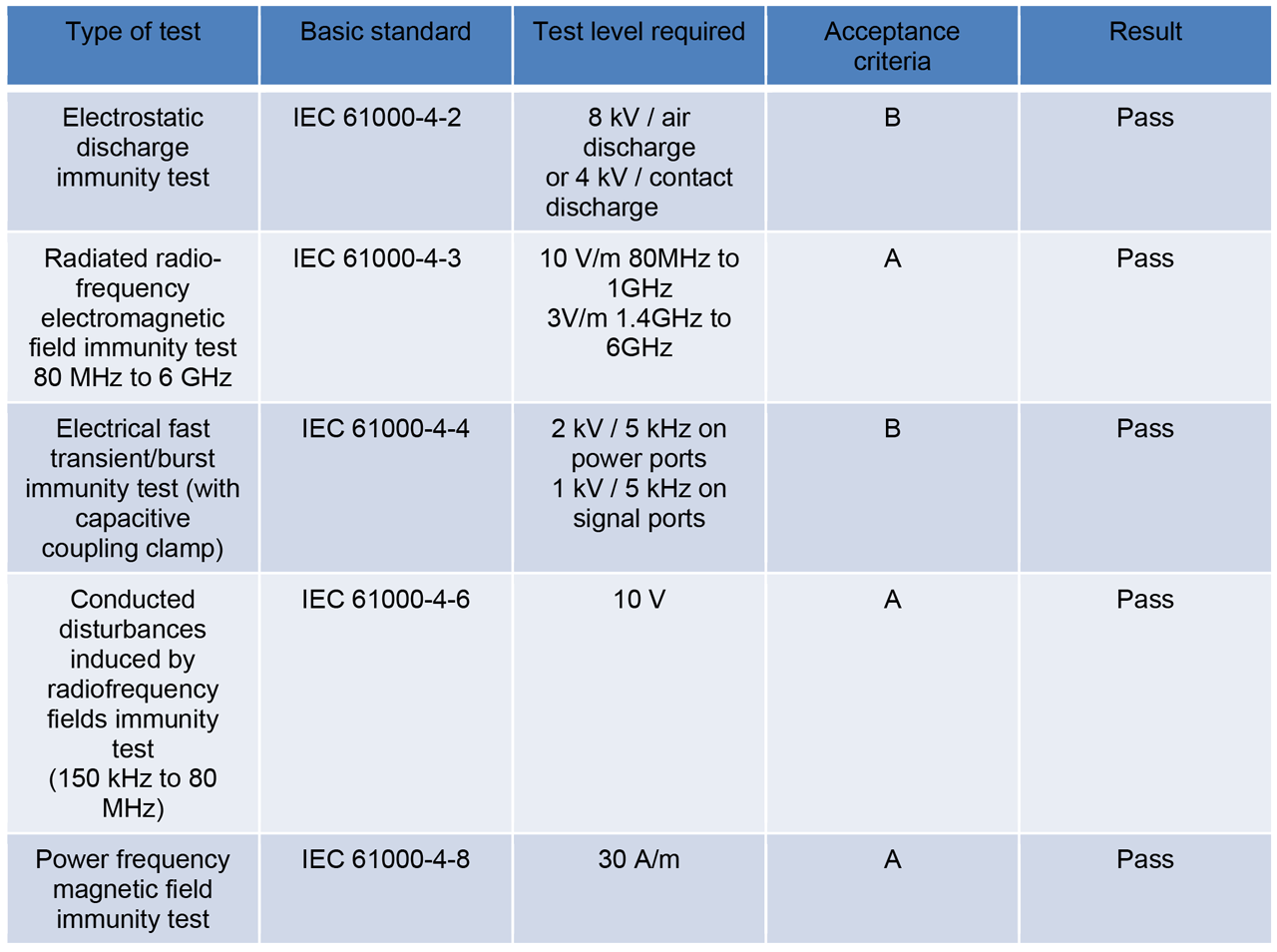
Table 2: Summary of Immunity Test Results for In-cabinet Devices
10BASE-T1M Overview
This overview is based on an unpublished standard and is subject to change.
The IEEE P802.3da project scope is to introduce “enhancements” to 10BASE-T1S multidrop mode. Much of the reason to add enhancements is to broaden the application space. Besides automotive and industrial panel wiring, there were requests from conveyance companies (elevators and escalators), overhead lighting, industrial for small in-field machine areas, and others. These applications potentially benefit from low-cost multidrop Ethernet if the reach and node count were increased. Switch vendor interest was in development of a more plug-and-play system.
While 10BASE-T1M is a PHY designator, the data communication format and signal levels are identical to 10BASE-T1S. T1S communication is re-used as the primary data component of T1M. There is often the wrong assumption that T1M replaces T1S and that T1S is obsolete. However, a primary objective is that the T1M PHY maintains compatibility when used along with T1S PHYs in T1S media systems.
In one enhancement, the T1M specification defines optional channel enhancements (tighter specifications) allowing increased distance (>= 50 m required) and node count (>= 16 required). Substantial work was done to simulate the multidrop media (the IEEE “mixing segment”). The increased distance and node count are recognized as achievable by compensation techniques. This approach was informed by and mirrors ODVA In-cabinet specification analysis and decisions.
The T1M media may be composed of a series of trunk sections, interconnected via interposing TCIs (Trunk Connection Interfaces), and terminated on each end. Each TCI may connect to a multidrop node and may contain compensation inductors. The In-cabinet media matches this structure and should exceed the requirements:
ODVA In-cabinet media is composed of a series of trunk sections (a continuous flat cable split by each connector), interconnected via interposing IDC connectors (TCIs), and terminated on each end. Each IDC connector connects to a node and contains inductive compensation).
The In-cabinet tradeoff of distance and node count is different, but it is likely that 50m and 16 nodes could be supported without any changes.
It is of note that IEEE did not specify any specific cable or connector for the T1M media enhancements. This is left to outside organizations.
Another enhancement is the optional plug-and-play multidrop power. IEEE Std 802.3cg-2019 did not specify multidrop power. The SPE term Power over Data Lines (PoDL) has caused a lot of confusion in the market. Likely IEEE will move forward with variants of Power over Ethernet (PoE) – which is better established in the market. IEEE P802.3da specifies Multidrop PoE (MPoE). The MPoE specification is not part of T1M (a data specification), but it is a compatible companion specification.
MPoE can operate on or separately from the communication pair. The MPSE (Power Sourcing Equipment) will not apply full power unless one or more MPDs (Powered Devices) are discovered. There are 30V (1W unit load) and 50V (2W unit load) system types. A multidrop supports up to 16 unit loads. Each device can consume up to 16 unit loads. The MPSE protects against faults. Energy is conserved if all devices are removed. Management of power is possible.
Another enhancement is the optional dynamic PLCA node ID allocation method. IEEE Std 802.3cg-2019 did not specify how PLCA node IDs were assigned, except that management interfaces were available for the purpose. A Dynamic PLCA (D-PLCA) method was invented. New nodes entering a system listen for PLCA beacons, and traffic. Then they try using PLCA slots to establish their IDs. There could be some collisions during the time the assignment is established. It is also possible to establish an initial or replacement coordinator. D-PLCA offers an improvement in multidrop performance with less management.
Another enhancement is optional multidrop Time Sync. It was previously demonstrated within IEEE that multidrop Time Sync could work with proper code in the Times Sync Service Interface (TSSI). Now it is “permitted” by the standard.
Another enhancement is the optional Link Layer Discovery Protocol (LLDP) management of the new features. This allows better management of a system where the switching infrastructure contains multidrop segments.
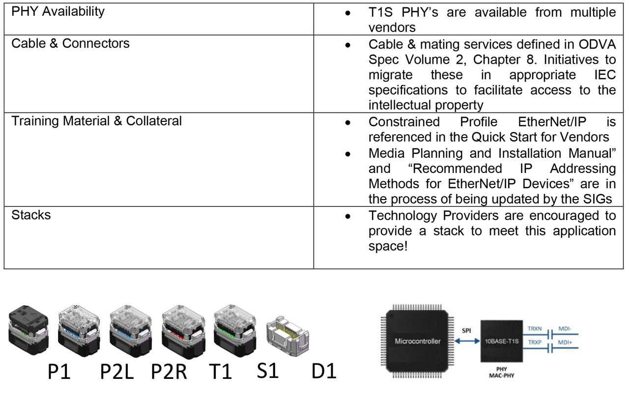
Diagram for In-cabinet Components
Potential T1M In-cabinet Enhancements
Potential usage is based on an unpublished standard and is subject to change.
It is possible that IEEE P802.3da multidrop enhancements (T1M and related specifications) will offer opportunities for In-cabinet enhancements. At the very least, a larger market drives lower chip costs and variety. Opportunities require further vetting.
While it is media enhancements (mixing segment specifications) that allow increased distance and higher node count, the specifications may drive PHY receiver improvements. The T1M mixing segment specifications are likely to be less stringent than ODVA specifications. It is possible that T1M PHYs will allow higher node count with existing In-cabinet media.
It is also possible that the increased distance would be valuable outside the cabinet. This would require an IP67 connector scheme.
The multidrop plug-and-play power could be considered. It may improve power management and conserve some energy. It could be used separately on NP and SP pairs.
In-cabinet already has an automatic PLCA allocation method that is compatible with real time control. D- PLCA has a method to specify a range of static PLCA node IDs. This offers the possibility of using the In- cabinet allocation to establish a real time range and to also allow other plug-and-play devices to enter the multidrop system in a non-interfering basis. An example is to plug a configuration or network monitoring tool into a multidrop system.
Time Sync is already possible for an In-cabinet system with proper drivers.
In-cabinet already uses LLDP for configuration and management purposes. Devices include support for specific ODVA TLVs for location, PLCA assignment, IP address management, and factory reset including security. IEEE specified LLDP could allow the broader OT system inventory to include In-cabinet segment information about power, PLCA, and location.
Broadening the In-cabinet Paradigm Beyond ODVA
Previous versions of EtherNet/IP have been incorporated into IEC standards. SPE-related ODVA specification updates (Ethernet-APL and In-cabinet) are not yet incorporated.
Since In-cabinet represents a paradigm shift from hardwired cabinets, it is believed to be beneficial to incorporate the In-cabinet media into IEC in a way that can be referenced by other SDOs.
A suggested integration strategy is outlined:
IEC 61918 Annex Q (1-pair Industrial Ethernet) can be amended and then referenced by IEC 61784-5-2 (CIP), IEC 61784-5-3 (PROFI), etc.
Extensions to Safety
The EtherNet/IP constrained profile as defined in the November 2024 release of the specification only covers standard devices without safety features. There are however a class of in-cabinet device that needs to have safety capabilities in addition to its core control function. An example of this is a motor starter which may require a safe torque-off function. As per the state of the art today, the functions of a motor starter are activated by applying power through a relay, with safety functions being achieved by the addition of supplementary components that are designed to remove power in the event that the equipment needs to return to a safe state.
It follows that as this class of In-cabinet device gains network connectivity, native safety connectivity may also be needed to allow the integration of the component into the wider safety system delivered by a programmable safety controller. In response, a technical evaluation has been conducted to understand how the constrained profile, or Volume 5 of the CIP Specification need to evolve in order to meet the use-case.
Safety: Initial Findings
An outline system architecture shows a pair of traditional emergency stop buttons which are wired to a CIP Safety input node. This Safety node is configured within a Safety controller, which in turn can also communicate with constrained safety nodes through a gateway device that converts the EtherNet/IP transport from full profile to the constrained profile.
Testing conducted with this architecture showed that the Controller to Device use-case is fully aligned with Volume 8 and that no changes are needed to the Safety Open, or to Safety I/O Messaging as a result of the change in the underlying transport mechanism.
The initial implementations of the Constrained Profile – for standard and secure connectivity – use a gateway device for conversion from full profile to constrained profile EtherNet/IP. These gateway devices have made use of Connection Aggregation for optimal use of resources – allowing for the multiple connections on the EtherNet/IP In-cabinet network to make sure of a single connection in the controller.
The Connection Aggregation Object (0xFA) today only addresses standard and secure connections, and does not support Safety. The technical evaluation showed that although independent safety connections from the controller to device worked in line with expectations there were challenges with scaling to large applications. Should future designs need to work using a similar architecture then Safety extensions will need to be added to the Connection Aggregation Object (or definition of a Safety equivalent).
Tools & Enablers
There are several enablers needed in order to bring an EtherNet/IP In-cabinet product to the market. The current state of availability is summarized in the table above.
Conclusion
The EtherNet/IP In-cabinet solution is a technology that brings wire reduction and information enablement to field level devices like simple industrial components, pushbuttons, contactors, etc. The single cable solution provides all appropriate electrical connections to each component to operate without the need to connect additional control wiring.
A significant advantage for EtherNet/IP In-cabinet solution is Ethernet connectivity all the way to field level devices. Controller will have direct access to data through controller tags and predictive maintenance can be performed on field level devices. User experience for adding In-cabinet devices to controller I/O tree is very similar to standard Ethernet devices, this will help enable a fast adoption of the technology by many OEM’s and end users who are already experienced with Ethernet technology. CIP security can be implemented by In-cabinet devices with resource constrained CIP security profile, this will help the In- cabinet system to meet stringent system level cyber security requirement in automation and control systems.
Bi-directional select line is another competitive advantage for EtherNet/IP In-cabinet solution. This minimized cable length used by panel builder with flexible cable routing from left to right or right to left. The select line enables topology discovery of all the end node devices. Users can perform simple device insertion and replacement without affecting other components/applications in the system. In-cabinet commissioning process is made simple and easy with the select line.
EtherNet/IP In-cabinet devices have demonstrated robust performance during EMC immunity tests that include fast transient burst, conducted immunity, radiated immunity, etc. In-cabinet devices are well suited for use in its intended industrial application environment.
EtherNet/IP In-cabinet technology is based on 10Base-T1S PHY and is future-proof with new emerging IEEE T1M In-cabinet Enhancements. New T1M PHY will maintain compatibility when used along with T1S PHYs in In-cabinet systems with additional potential benefit of node count increase and cable length increase.
Since the introduction of EtherNet/IP In-cabinet technology to the market, there have been growing interests to include safety products as parts of In-cabinet portfolio. CIP Safety can be implemented based on In- cabinet technology to include Safety Estop and Safety Contactor, etc. Initial investigations suggest that the CIP safety implementation for In-cabinet device is fully aligned with Volume 5 CIP Safety specification.
EtherNet/IP In-cabinet infrastructure components are available for mass production. There are T1S PHY (SPI interface, MII interface) choices from multiple vendors on the market now and many more T1S PHY options (OA-3P interface) in the pipeline. Cable and connectors are available for mass production. There are different ODVA collateral documents available for users and implementers. All the required components and documentations are available for launching the EtherNet/IP In-cabinet products to the market.