

TechnologyMay 20, 2024
General Purpose Single Pair Ethernet for Process Instruments

General purpose SPE continues the trend of using SPE to displace fieldbus, sensor, and device networks, along with enabling networking of hardwired devices and devices from point-point links. A complete portfolio of instruments is envisioned and desirable for both hazardous and non-hazardous locations.
ODVA has demonstrated industry leadership in Single Pair Ethernet (SPE) solutions. External promotion included liaison with IEEE P802.3cg project, and active stakeholder position in the APL Project. Domain- specific specification EtherNet/IP enhancements include an In-cabinet SPE solution (motor control components), and Ethernet-APL (process instruments for hazardous locations).
Further specification enhancements are underway in the EtherNet/IP Physical Layer Special Interest Group for “GPSPE” (general purpose SPE). One intent of GPSPE is to utilize 10BASE-T1L to extend SPE use cases – by reaching out from inside the cabinet and into non-hazardous field locations.

Another intent of GPSPE is to reference existing/emerging SPE standards rather than invent new technology. GPSPE will be useful to expand the application space of EtherNet/IP for constrained devices across industrial domains (discrete, hybrid, and process automation) – reducing the end-device electronics and field cabling. This paper discusses use cases and benefits when utilizing GPSPE with new Process Instruments.
This article also discusses minor changes that allow – EtherNet/IP end-devices using Ethernet-APL to interoperate with other GPSPE devices.
Evolution of Industrial Ethernet
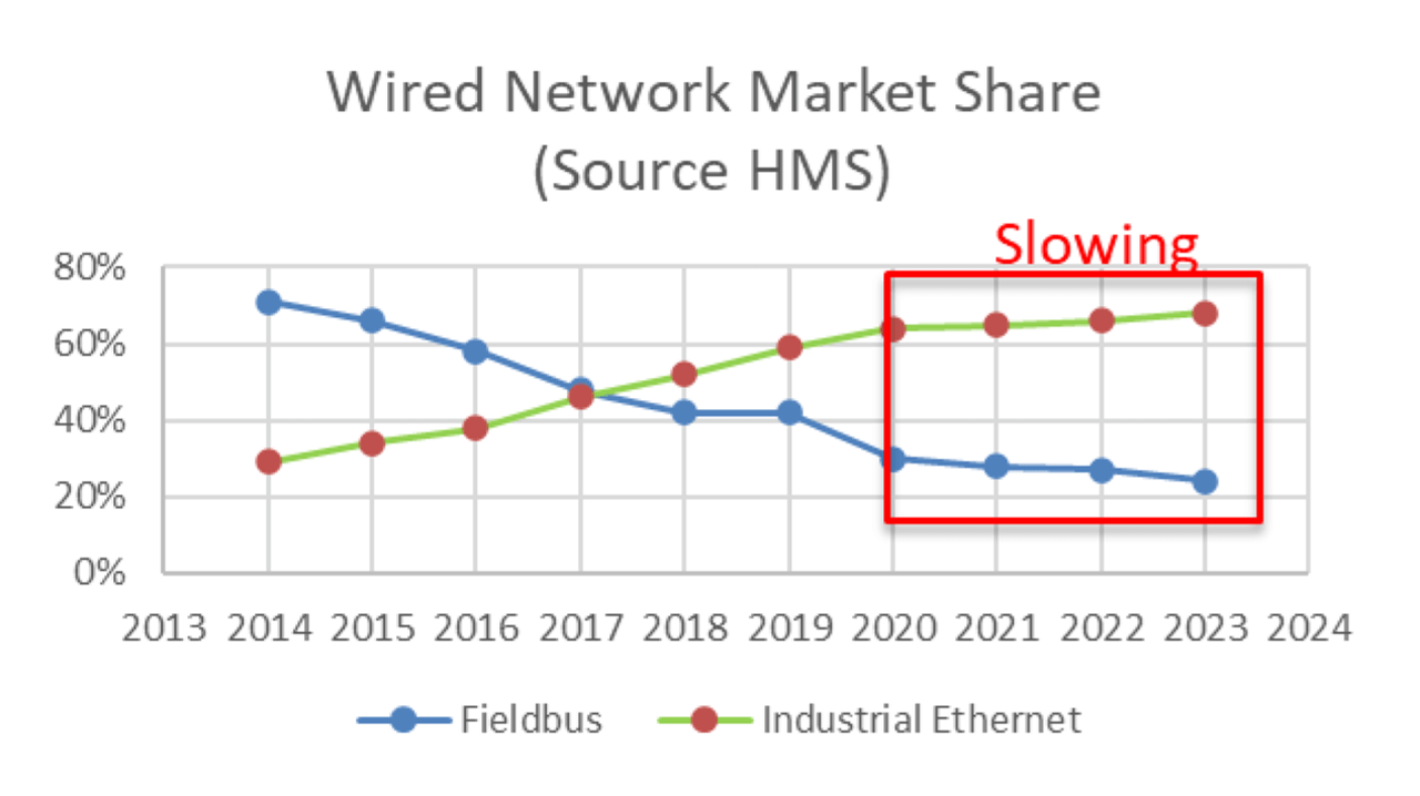
Figure 1: Industrial Ethernet and Fieldbus market share over time.
Industrial Ethernet solutions emerged rapidly in the decade from 2000-2010. As shown in Figure 1, high growth led to the steady displacement of many fieldbus and sensor networks, however, complete transition has been hindered by cost and features.
Pursuing higher performance, much of Industrial Ethernet is in transition from 10 and 100 Mb/s over two- pairs to 1 Gb/s over four-pairs. While the cabling cost increases, there are also substantial cost, size, and power increases in the magnetic coupling circuits, EMC protection circuits, and PHY packaging.
Application to small devices (often hardwired) is then limited.
Additionally, multipair Industrial Ethernet is limited in distance to 100 m, does not power the sensor, and is not directly compatible with hazardous environments. Therefore, multipair wiring is generally not accepted in the field networks and limited in its application to Process Automation use cases.
The multipair Industrial Ethernet limitations and direction make it increasingly difficult to displace some fieldbus and sensor networks, and to achieve the transition from hardwired devices to networked devices. The result is a network with non-homogenous communication, a variety of technologies that are not familiar to most graduates, limited data flow, and lack of end-to-end security. Therefore, engineering and operations face additional costs and efforts for commissioning and maintenance of this mix of technologies.
SPE has emerged as a potential response to displace the remaining fieldbuses, sensor networks, and some hardwired solutions at the edge of the network.
Automotive pioneered SPE when they realized that the wiring harness had become the third heaviest component in the car. They also realized that the number of types of networks in the car (overlapping cables in the wiring harness) was continuing to expand. A further realization was that useful information was trapped in these separate systems. (An example is that the wheel speed sensor could be used with the GPS system to track location in a dark tunnel and turn headlights on and off on entry and exit.) Secure networking has become another requirement.
The automotive industry began to aggressively pursue an all-Ethernet vehicle. SPE solutions were standardized within IEEE to cover a range of speeds from 100 Mb/s to greater than 10 Gb/s.
The automotive vision was compelling and led industrial automation organizations to become engaged in IEEE to develop SPE that was suited to industrial scale and needs. The result was IEEE Std 802.3cg- 2019. There were two new SPE PHYs introduced in that standard. 10BASE-T1L is used in Ethernet-APL to meet requirements for long distances and for intrinsically safe implementation. 10BASE-T1S was driven by both automotive (primary) and industrial to achieve a lowest cost solution for Ethernet. Like with CAN in DeviceNet, industrial can leverage automotive SPE volumes.
Beyond the IEEE standard, there has been standardization of cables and connectors. There is also on- going standardization within industrial organizations – including ODVA. Multiple silicon vendors have introduced PHYs. Devices are in development and poised to emerge.
Published ODVA Specifications Leveraging SPE
ODVA has demonstrated industry leadership in Single Pair Ethernet (SPE) solutions. External promotion included liaison with IEEE P802.3cg project, and active stakeholder position in the APL Project.
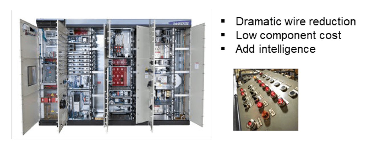
Figure 2: SPE domain and challenges for In-cabinet solution.
One ODVA domain-specific SPE solution is an EtherNet/IP specification for cabinets containing motor control components. This is depicted in Figure 2. The specification is included in Chapter 8-10 “Industrial EtherNet/IP In-cabinet Bus Media and Physical Layer”.
Another ODVA domain-specific SPE solution is an EtherNet/IP specification for process instruments for hazardous locations. This is depicted in Figure 3. The specification is included in Chapter 8-11 “EtherNet/IP Media and Physical Layer for Ethernet-APL (Ethernet Advanced Physical Layer)”.
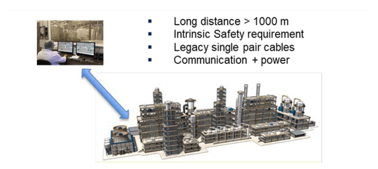
Figure 3: SPE domain and challenges for process automation solution.
ODVA General Purpose SPE (GPSPE) Initiative
The EtherNet/IP Physical Layer Special Interest Group is developing EtherNet/IP Specification Enhancements (ESEs) for General Purpose SPE (GPSPE). One reason to call it “general purpose” is the intent of GPSPE to reference emerging standards, including IEEE Std 802.3-2022 (as amended by IEEE Std 802.3cg-2019), ISO/IEC 11801-3 AM1, ANSI/TIA 568.7A, and IEC 63171 – rather than invent new technology. The current effort is to reference 10BASE-T1L.
One intent of GPSPE is to extend the SPE application space of EtherNet/IP for constrained devices across industrial domains (discrete, hybrid, and process automation) – reducing the end-device electronics and field cabling.
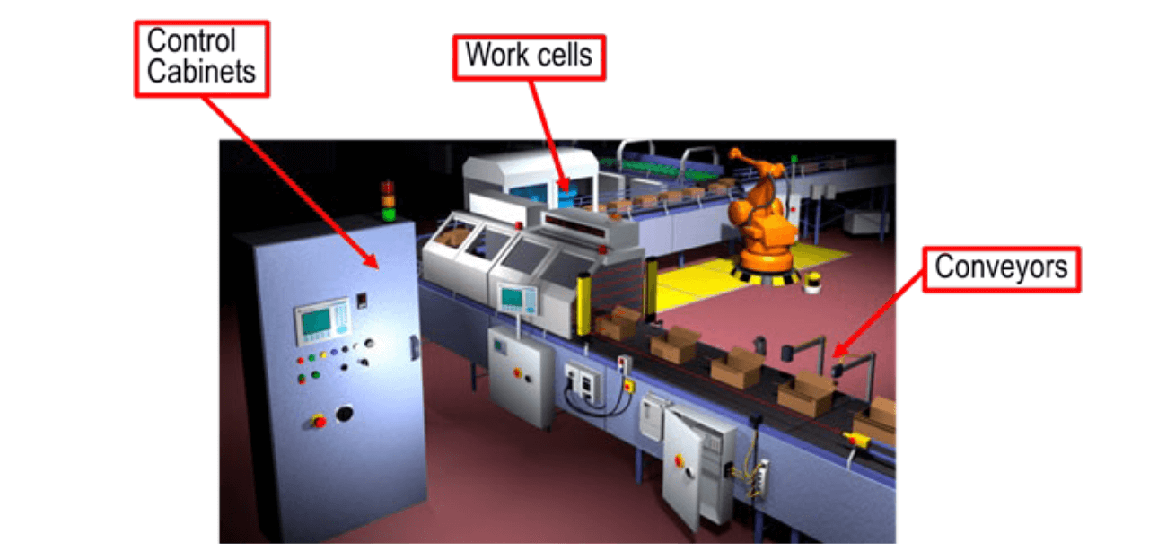
Figure 4: GPSPE non-hazardous domain – reaching from cabinets into the field.
One GPSPE use case is to reach out from the control cabinet and into non-hazardous field locations. This is depicted in Figure 4 for discrete automation. Note that Ethernet-APL can reach out from a cabinet and into the field – for hazardous locations.
Since GPSPE is an on-going effort, many decisions have not been made or are subject to change.
Relation of GPSPE to EtherNet/IP for Constrained Devices
EtherNet/IP for constrained devices includes both:
Reduced physical layer
- Reduced Cabling
- Connectors
- Coupling circuit
- EMC protection
- SPI MAC/PHY interface
Reduced protocol stack
- Less FLASH and RAM for smaller MCUs
- Transport (UDP-only)
- Security (DTLS-only)
GPSPE specifies a reduced physical layer. Devices can also implement the reduced protocol stack.
GPSPE Use Cases for Process Instruments
Non-hazardous instrument applications include many Process Skids (e.g., as shown in Figure 5). These skids are often specialty OEM modules that are shipped and placed at an end site. The skids may be interconnected via piping and supervisory communication to perform a series of production functions. The distances are short. These OEM applications are cost sensitive.
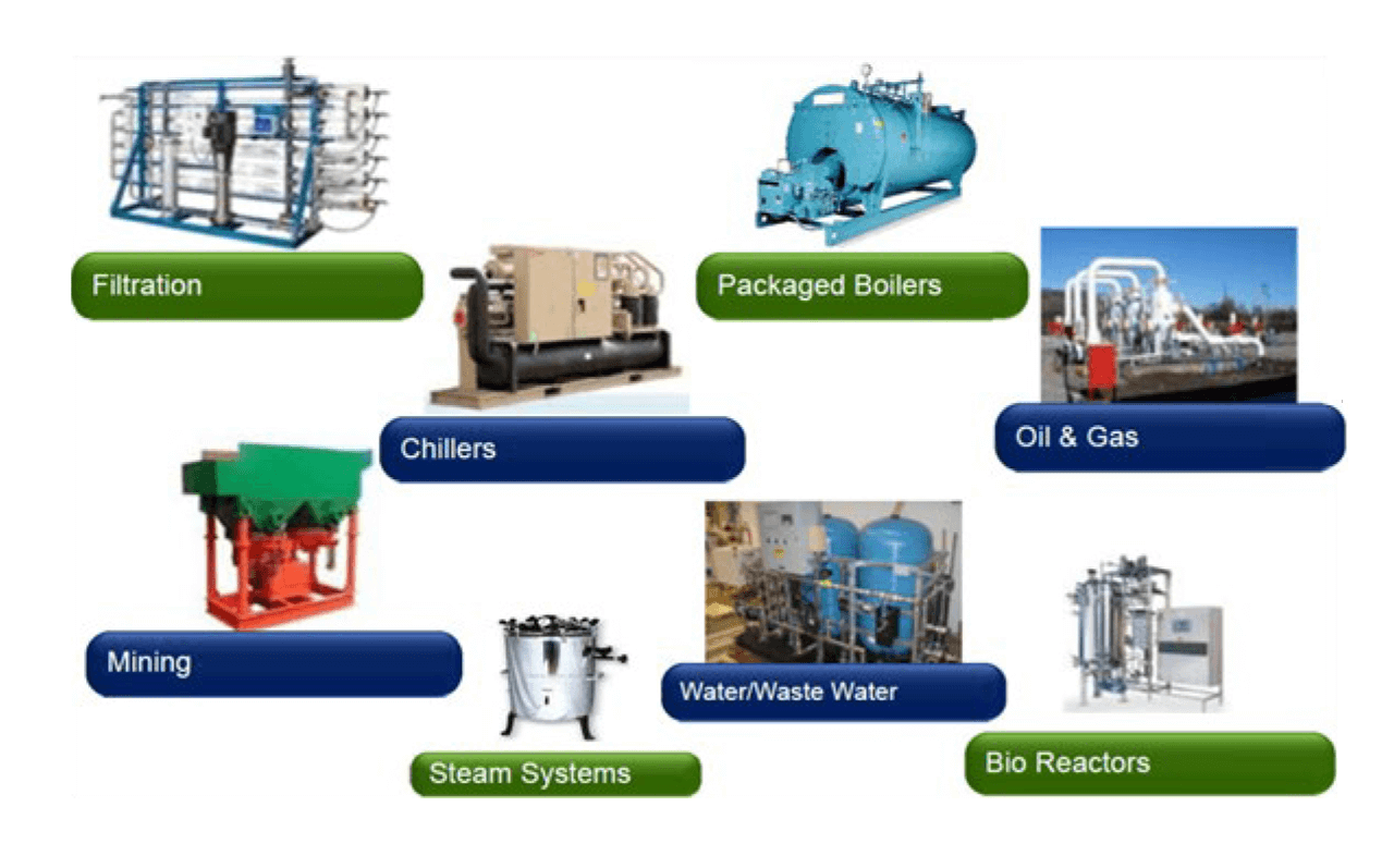
Figure 5: Many Process Skids utilize instruments in non-hazardous locations.
Other non-hazardous instrument applications are included in the plantwide automation for Life Sciences, Food and Beverage, and Water and Wastewater industries, as depicted in Figure 6. These industries may utilize skids as elements a larger plant. The distances are larger than on skids, but smaller than with large plants like in Oil and Gas.

Figure 6: Industries where instruments are prevalent in non-hazardous locations.
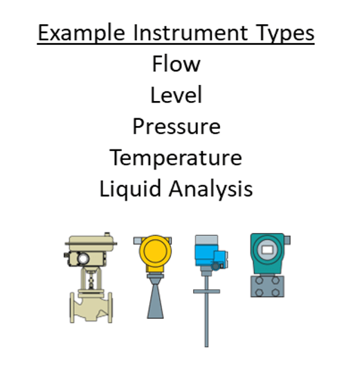
Figure 7: Instrument types.
The introduction of SPE (Ethernet-APL) is driving all instruments toward Ethernet connection in hazardous areas. Harmonization on a full suite (see Figure 7) of EtherNet/IP instruments has numerous advantages:
- Fast updates
- Reduction of gateways
- Reduction of cabling – single pair with power
- Increased information capability from some instruments
- Ability to have multiple measurements from the same instrument.
Non-hazardous locations do not yet have a full suite of SPE-based EtherNet/IP instruments. A limited set of EtherNet/IP instruments is sometimes utilized. These instruments are typically supplemented with HART instruments when no equivalent EtherNet/IP instrument is available.
GPSPE could drive all instrument types toward Ethernet connection within non-hazardous areas.
GPSPE Power Classes
GPSPE will reference IEEE Std 802.3-2022 Clause 104 (PoDL) for power options. The PSE and PD are Type E, allowing longer distances.
Classes 10-15 will be used (see Figure 8). These were added within IEEE for long reach (1000 m) and industrial usage. Classes 0-9 exist primarily for short reach (15 m) and automotive usage.
Both Plug and Play and Engineered power are being considered.
Comparing GPSPE with Ethernet-APL for Process Instruments
GPSPE shares basic Ethernet technology with Ethernet-APL, but each has optimizations for different industry segments. Table 1 compares multiple aspects of GPSPE and Ethernet-APL. Both support EtherNet/IP communication over 10BASE-T1L. Differences primarily relate to the Ethernet-APL requirement to operate in hazardous locations. This leads to intrinsic safety requirements, which lead to a custom engineered power solution.
| GPSPE (subject to change) | Ethernet-APL (published specification) |
|---|---|
| Physical Layer for EtherNet/IP | Physical Layer for EtherNet/IP 10BASE-T1L (initial PHY) 10BASE-T1L |
| Non-hazardous locations | Hazardous locations |
| No extra IS hardware | Extra hardware for IS protection |
| Plus-and-play power (device detection, voltage/power negotiation). Engineered power option | Engineered power (directly applied) |
| 60 Vdc tolerance (from 10BASE-T1L) | 60 Vdc requirement precluded, must operate up to 15 Vdc |
| Classes 10-12, 30 Vdc, up to 8.4 W Classes 13-15, 30 Vdc, up to 52 W |
9-15 Vdc, 0.5 W or 1 W |
| Connectors and bulkheads | Terminal blocks and cable glands |
| No IS certification or marking | IS certification and marking |
Intrinsic Safety Comparison of GPSPE with Ethernet-APL
Ethernet-APL devices and switches are specified for hazardous locations as found in Oil and Gas, and Chemical industries. The inclusion of intrinsic safety in Ethernet-APL devices requires a level of redundant hardware for protection against faults that can cause hazardous conditions. The amount of hardware increases with higher power levels. Switches supply power for multiple devices and have larger overhead.
GPSPE will be specified for non-hazardous locations. This reduces the redundant hardware and eliminates a major certification process. As a result, the GPSPE field device and switches are expected to be more cost efficient than the Ethernet-APL field devices and switches.
Ethernet-APL power and voltage are quite limited due the intrinsic safety requirements. Power Class A (Ex ia IIC) provides 0.5 W @ 15 V to a device. Power Class C provides 1 W @ 15 V to a device, but only for less hazardous environments (Ex ic IIC).
While these power levels are sufficient for most of the sensor instruments in the field, there are still specific instruments, such as flow meters, that benefit from more power and therefore require secondary power supply. The secondary source would itself need to be compatible with the hazardous location. This could mean a second identical cable run (also low wattage) that might be run for 200 m. As an alternative, the power cable may be run in an expensive explosion-proof conduit and extra measures taken in the device. Already Ethernet-APL is a large step up from 4-20 mA or HART, but the power budget is still below the optimal level.
On the other hand, GPSPE does not have these power restrictions, as no intrinsic safety requirements needs to be fulfilled. To power typical process sensors known in the non-hazardous industries, an 8 W power budget is desirable. In most cases this is sufficient even for demanding flow sensors.
GPSPE is expected to specify PoDL (Power over Data Line) Classes 10,11 and 12. An SPE switch implementing the PSE (Power Supply Equipment) function would source 30 Vdc and deliver up to 8.4 W to a PD (Powered Device). The switch itself may operate from and distribute power from a higher powered GPSPE link or from separate power.
Extension of GPSPE with Ethernet-APL devices
While the ODVA GPSPE specification is still in development, the specification for EtherNet/IP for Ethernet-APL has already been published. Vendors are currently preparing Ethernet-APL Field Devices (and switches) for the market.
There are advantages in enabling these Ethernet-APL devices to be able to attach to GPSPE:
- Hardware platform and firmware re-use
- Faster launch of GPSPE
Other devices might be specifically optimized (i.e., without Intrinsic Safety or utilizing more power) for GPSPE.
Ethernet-APL and GPSPE devices are potentially interoperable via switching (both are EtherNet/IP over 10BASE-T1L). However, the power systems are different. Subsequent sections discuss the differences.
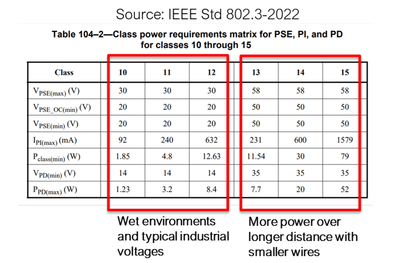
Figure 8: GPSPE Power Classes.
Figure 8 illustrates the concept of an optional “compatibility mode” between Ethernet-APL and GPSPE. An Ethernet-APL device that supports compatibility mode could operate with either switch.
Compatibility mode has the following attributes for Ethernet-APL field devices:
- Device is able to operate at a higher GPSPE voltage level
- Device is not damaged by the increased voltage
- Device follows GPSPE connector scheme
- Device labelled properly for non-IS locations
Compatibility mode has the following attributes for GPSPE switches:
- Can be configured to apply power directly to Ethernet-APL field devices
Harmonizing GPSPE and Ethernet-APL power
The GPSPE PSE would normally interact with the PD and not turn on full voltage unless a PD is present on the link. Various interaction methods are possible. The first method is Detection. A low voltage signal is placed on the link by the PSE and a PD will draw a specified current if present. The PSE must be pre- configured to supply a specific voltage and power (i.e., it is set to a specific Class). A second method is Classification, where information is exchanged between PSE and PD. This also allows PD detection – as well as the establishment of the Class without pre-configuration.
Unfortunately, unmodified Ethernet-APL devices do not support Detection or Classification. The Ethernet- APL Source (power supply to a link) is directly enabled to the Ethernet-APL Load (powered device on a link) – regardless of whether a device is present. The circuitry for PoDL was never specified for intrinsic safety. Additionally, the PoDL circuitry would potentially cut into the limited Ethernet-APL power budget.
One simple method for powering Ethernet-APL devices in a GPSPE system is known as PoDL-bypass. The PSE is pre-configured to provide a full voltage to the link without Detection or Classification.
The PSE Source utilizes PoDL coupling circuit and a subset of the state machines.
PoDL-bypass considerations – damage
The pre-configured voltage in PoDL-bypass could be specified as 30 Vdc (Class 10-12) and/or 58 Vdc (Class 13-15). It is important to prevent damage.
GPSPE is expected to support both PoDL voltages and to retain the IEEE requirement for 10BASE-T1L is to tolerate up to 60 Vdc. GPSPE devices could never be damaged by direct application of 58 Vdc.
Ethernet-APL devices are not required to tolerate 60 Vdc. Ethernet-APL Field Switches Classes A and C only supply 15 Vdc to the Field Devices. This voltage and the matching current fit under the ignition curves (limits to not ignite an explosive atmosphere) and were found as optimal in power delivery. Some vendors have mentioned implementing non-replaceable fusing that would open before even reaching 30 Vdc. Other vendors may not have the fuse problem.
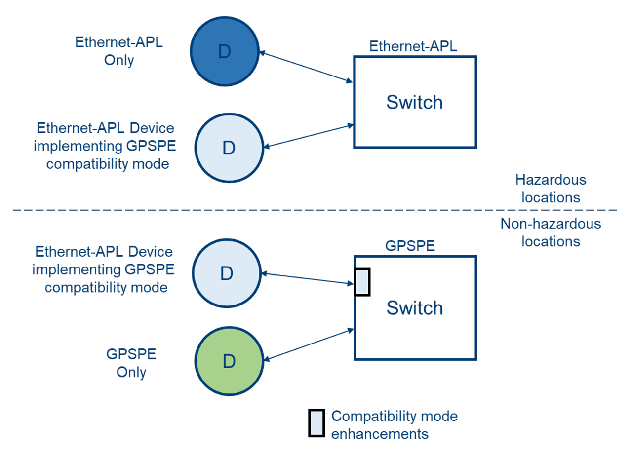
Figure 9: GPSPE compatibility mode for Ethernet-APL.
PoDL-bypass considerations – voltage selection
It is proposed that GPSPE only specify a PoDL-bypass option for Classes 10, 11 and 12 (30 Vdc). An Ethernet-APL device could be powered in a GPSPE system – if it operates from and tolerates 30 Vdc. Limiting the pre-configuration voltage to 30 Vdc and designing the Ethernet-APL device to operate from and tolerate this voltage would preclude damage.
Pre-configuration of 58 Vdc may not have an advantage. 8 W is considered adequate. The non- hazardous applications do not require 1000 m distances. Likely 200 m is adequate. Class 12 voltage drop across a 200 m cable must meet the 9.5 Ω loop resistance. For a 400 m loop, we have 0.024 Ω/m (i.e.,18 AWG wires).
Design for operation/tolerance is considered more difficult. The component ratings are higher in comparison to the 15 Vdc usage, sizes are larger, and heat dissipation is likely a concern.
Additional qualification and installation restrictions may also apply when exceeding 50 V due to potential shock hazard. This is especially true for wet installations.
PoDL-bypass considerations – misapplication
A related issue concerns moving an Ethernet-APL instrument between hazardous and non-hazardous locations. When the device is placed in the non-hazardous location, there is no guarantee the device will not sustain hidden faults. When placed back in a hazardous environment, the device may not perform as intended.
It is required that for Ethernet-APL devices to be used with GPSPE, the devices are packaged and labelled without hazardous area approval markings. It is also proposed that GPSPE avoid re-use of the Ethernet-APL specified M8 and M12 connectors. These measures reduce the possibility of misapplication and still allow the bulk of the hardware and firmware to be re-used.
Conclusions
GPSPE continues the trend of using SPE to displace fieldbus, sensor and device networks and to enable networking of hardwired devices and devices from point-point links. Non-hazardous process applications are prevalent.
A complete portfolio of EtherNet/IP instruments is desirable for:
- Hazardous locations (Ethernet-APL)
- Non-hazardous locations (GPSPE)
GPSPE is anticipated to bring advantages to Process Instruments in non-hazardous locations:
- Reduced wiring
- Lower cost by eliminating Intrinsic Safety
- Significant power
While there is advantage in allowing Ethernet-APL instruments to be interoperable with GPSPE, they must be designed appropriately.