

TechnologyJanuary 12, 2023
Ongoing developments with xDS device descriptions
The development of Digital Device Description technology will lead to a more robust and secure device description than is currently available. Moving ahead, efforts at ODVA are continuing toward development of xDS, the publication of both an xDS specification and tools needed to prove these concepts.
The ODVA Special Interest Group for xDS Digital Device Descriptions is working to develop a specification for next generation of device description as a robust, extensible, and secure artifact.
This article describes the state of the art in the development of xDS and details about the use of AutomationML constructs to describe components, the use of Open Packaging Conventions to package the various components, security approaches, and proposed tools to ease the adoption of xDS.

Introduction
With ever-increasing interconnectivity of machines and processes, and escalating demands for device data, the need exists to provide a more robust and secure device description for CIP™ devices than can be achieved using the current EDS file. Initiated February 2019, the xDS Digital Device Descriptions SIG has been working on developing such a replacement.
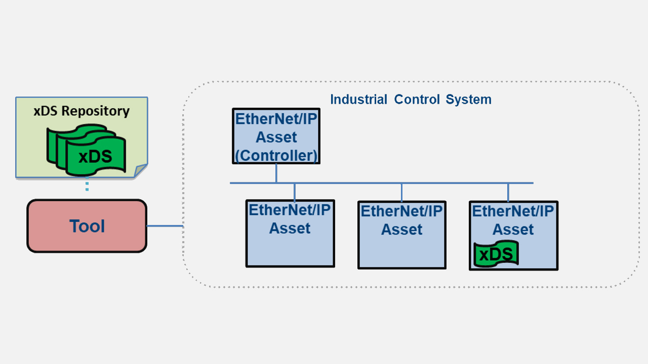
The goal is to provide a scalable digital device description which is as simple and reusable as possible while still providing a means of representing the rich, robust information provided in CIP. The xDS artifact provides the necessary information to tools to be able to configure, monitor, control, diagnose, and conformance test CIP devices in an Industrial Control System (ICS) over the network. The primary workflows for which xDS provides information to the tool are:
- Network and Security Configuration
- Device Configuration
- Network Diagnostics
- Device Diagnostics
- Device Conformance
Similar to EDS files, the xDS artifact may be embedded within the device itself or provided through some other external means such as a website or device description database. While xDS is being designed to be applicable to any CIP network, the primary focus at this time is for EtherNet/IP networks.
This article represents the understanding and proposal for the xDS representation, as developed by the xDS SIG for the latest ODVA technical conference. Four main topics will be discussed. First, the use of AutomationML constructs is presented as a basis for modeling device information such as features and configuration parameters.
Second, a packaging scheme and format is presented for aggregating various components of differing formats into a single, compact, logically arranged artifact. Third, a discussion of security considerations and the proposed approach, and finally, a proposal for some tools to aid in the adoption of xDS.
Choice of AutomationML as Device Description Modeling Language
The xDS SIG investigated several approaches for representing device description information and has settled on the use of AutomationML (AML). AutomationML is an XML based, object-oriented data modeling language developed for representing plant engineering information, based on the representation format of CAEX as defined in IEC 62424. AML is an open standard, and its specifications may be implemented on a royalty-free basis.
AML is a logical choice as the base description language for xDS, as it was developed specifically for the purpose of automation data exchange. It uses existing industry data formats specifically designed for storage and exchange of different aspects of engineering information. AML interconnects engineering tools.
The AutomationML Organization supports and maintains AutomationML. This organization has celebrated its 15th anniversary. Membership has continued to grow within the AutomationML Organization highlighting the stability and improvement of the organization as a standards consortia. Several technologies related to the automation industry have already adopted use of AML, such as the Asset Administration Shell for Industrie 4.0.
AML has a defined structure which is flexible and extensible, allowing predefined ODVA structures to be built on top. Additionally, some tooling has already been implemented to simplify the development of xDS. The AutomationML Editor provides a logically oriented, graphical tool to aid in the initial design and testing of xDS concepts. The AML Engine library provides a freely available library based on the .NET framework for processing and editing AML files. Because AML is based on the XML format, support for platforms other then .NET can easily be adapted, and many have already been demonstrated.
Modeling CIP Devices Using AutomationML
Details about AutomationML are beyond the scope of this paper. However, the following basic AML concepts are required to understand the xDS approach. There are three types of AML classes used by xDS:
- Role Class: Provides abstract semantic information about an object.
- System Unit Class: Represents a specific type of object. A System Unit Class can reference one or more Role Classes to represent the roles the object performs.
- Interface Class: Models an interface between components.
Each of these types of classes can be collected into libraries of similar classes and can inherit from other classes in the same library or from another referenced library. Along with these class libraries, AML allows the definition of custom attributes, collected into an Attribute Class library. A set of common AML base libraries are defined, from which more specific classes can be inherited.
For xDS, a set of standard libraries is created from the AML base libs to define the Role Classes, Interface Classes, and custom CIP attributes required to describe a CIP device. These libraries comprise the ODVA xDS Primitives, which will be an ODVA-provided reference library to be used by any tools creating or interpreting an xDS. Specific device descriptions are created as a System Unit Class referencing the CIP role classes and interface classes. The format of this device description will be defined in the xDS specification (noted in Figure 2 as the CIP Device Description Model). This creates a layered approach, as shown in Figure 2.
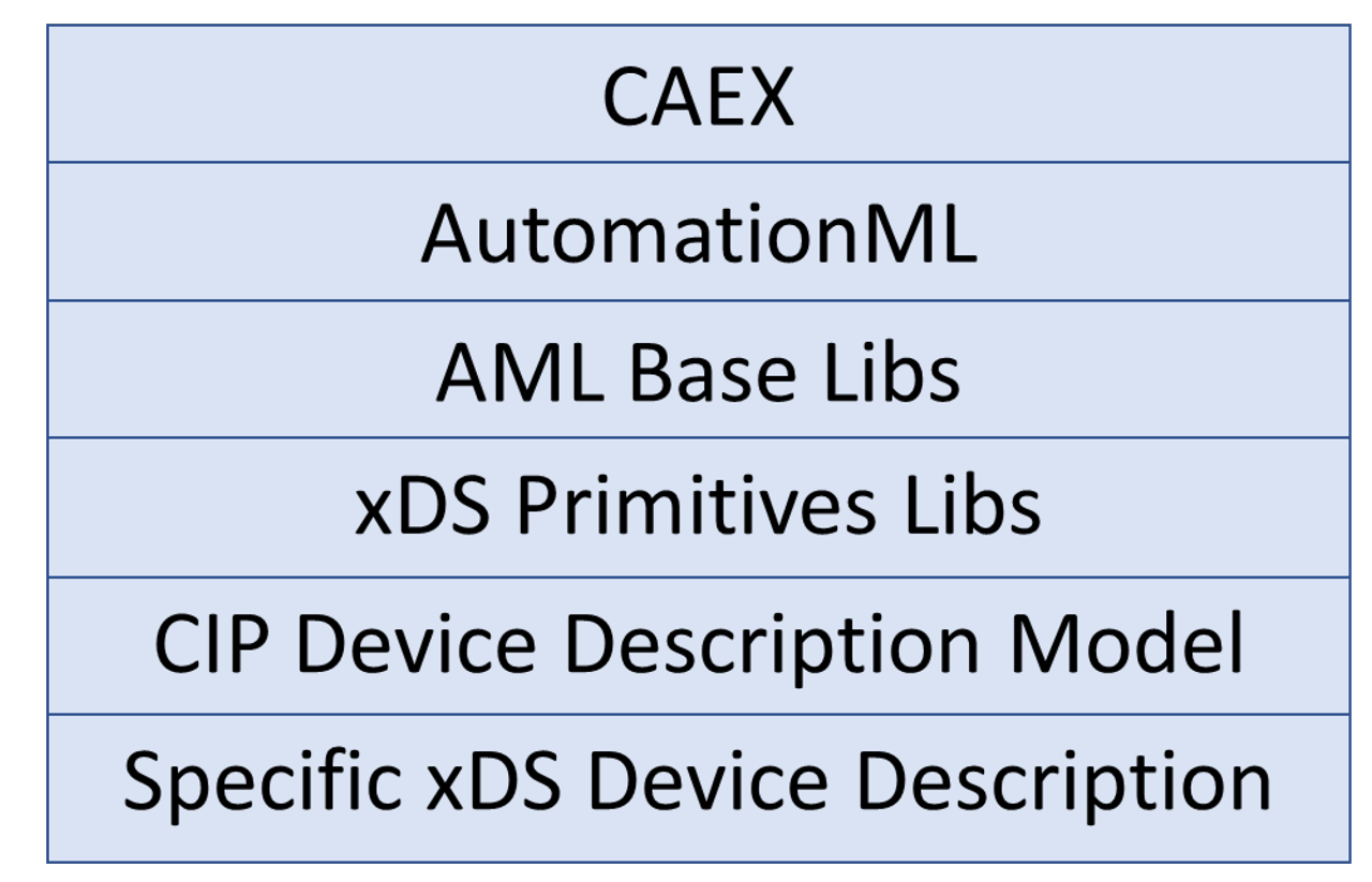
Figure 2 – xDS Layers
Figure 3 shows the interactions between these components, where a specific xDS device description references the ODVA xDS Primitives definition file, and any tool interpreting the xDS will require the primitives to fully understand the xDS definitions.
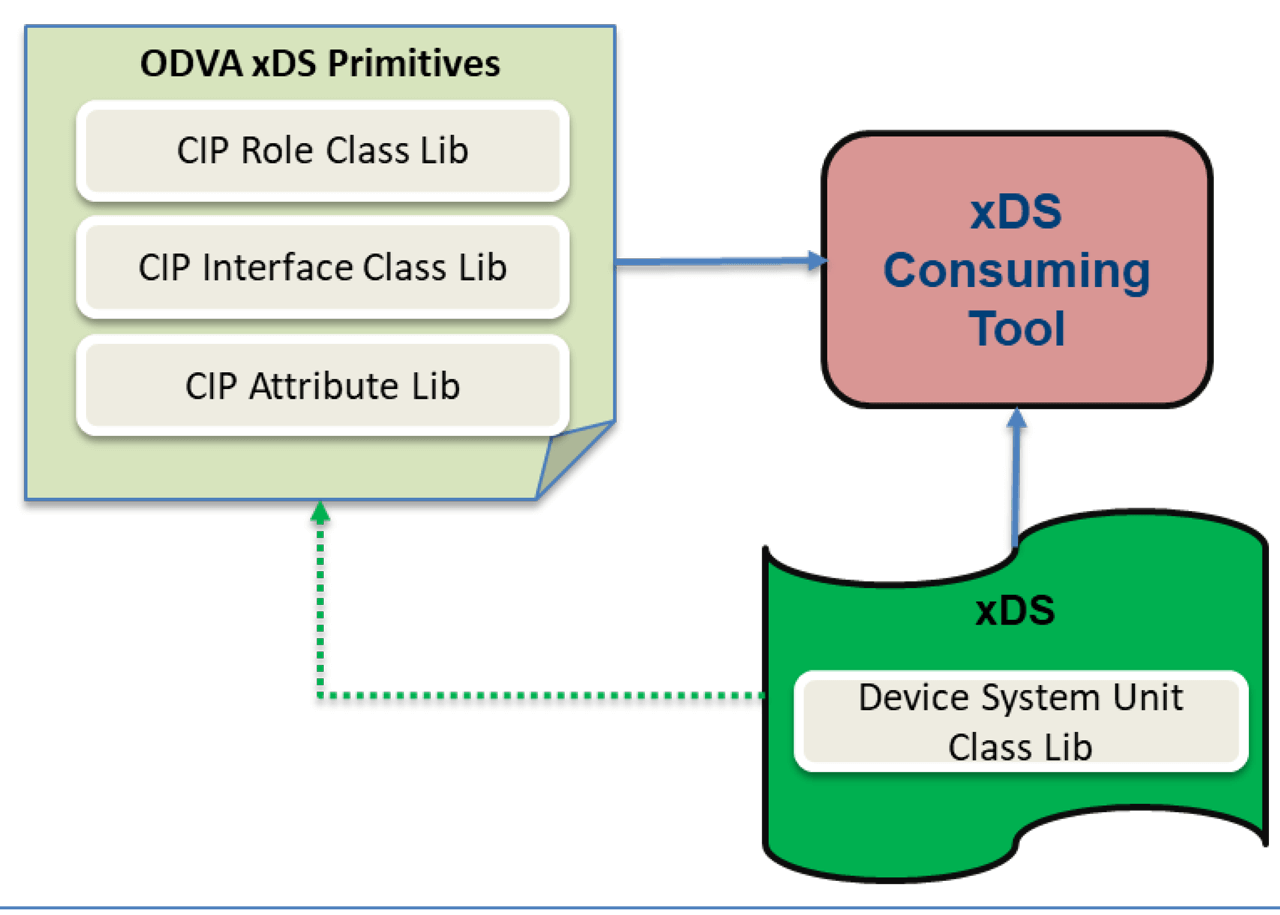
Figure 3 – Interaction of xDS and ODVA xDS Primitives
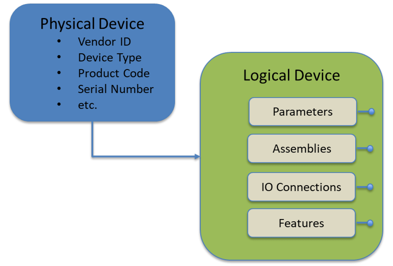
This structure is accomplished through a set of custom Role classes in the ODVA xDS Primitives library which inherit from the AML CommunicationRoleClassLib. The physical device is modeled inheriting from the AML PhysicalDevice Role class, and attributes are defined for required CIP device identification. The inherited role classes EtherNetIPDevice and DeviceNetDevice provide a means of distinguishing between the two. (It should be noted that xDS development is focusing on EtherNet/IP, but efforts are being made to ensure that the design is able to be adopted to DeviceNet in the future). Figure 5 shows the physical device role classes and associated attributes, as visualized using the AutomationML Editor.
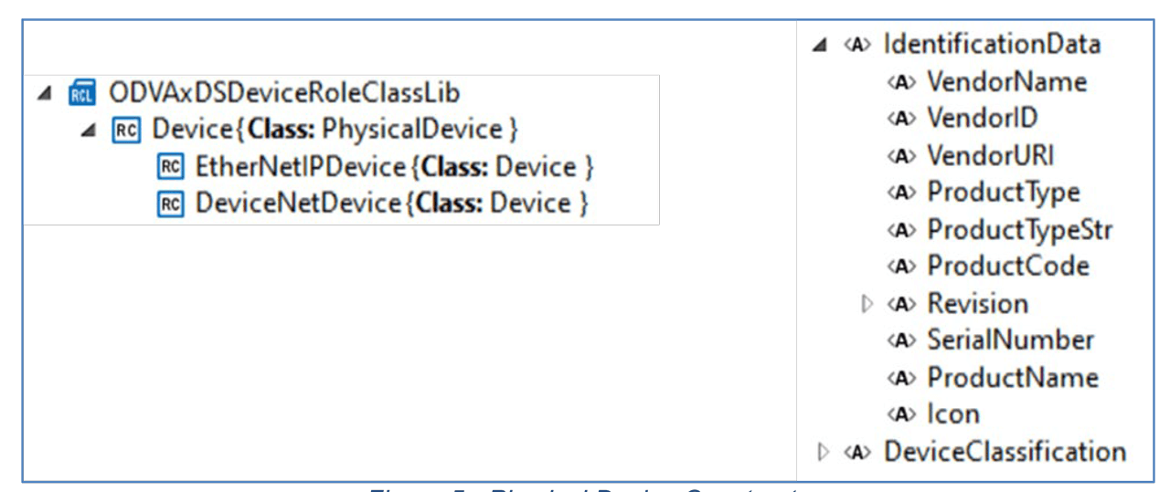
Figure 5 – Physical Device Constructs.
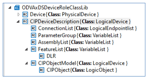
The logical device is modeled as CIPDeviceDescription, inheriting from the AML LogicalDevice Role class. The logical device is further broken down into several collections of components. The ConnectionList collects a list of supported IO connection definitions. The ParameterGroup component is used to collect a list of Parameter definitions. Multiple ParameterGroup instances may be included as a means of grouping common parameters together. Likewise, the AssemblyList component is used to collect a list of Assembly interface definitions. Multiple AssemblyList instances may be included. The FeatureList component is used to collect predefined feature declarations, such as DLR support. Finally, the CIPObjectModel role class provides constructs to declare the entire CIP Object model supported by the device. This is used to declare all supported public CIP objects with declaration of supported attributes and services. Details about how the FeatureList and CIPObjectModel components will be modeled have not yet been determined. See Figure 6.
Three custom interface classes are defined in the xDS Primitives file for modeling the key CIP interfaces to device configuration information. The Parameter interface class is used to declare configuration parameters in the same way as the EDS ParamN. By leveraging AML constructs and flexibility, the ability exists to define parameter dependencies, complex range requirements, multi-language help strings, International Registration Data Identifier (IRDI) references, and other custom information to the parameter. The Connection interface class provides constructs to declare supported I/O connections. Finally, the Assembly interface class is used to declare supported assemblies and their data layout. Figure 7 shows interface class library entries.
CIP Device Model Example
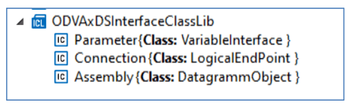
Figure 7 – Interface Classes.
A simple reference device based on a software simulation of a General Purpose Discrete IO is used to demonstrate creating an xDS device description. The device consists of four discrete input points and four discrete output points, and follows the device profile as described in Volume 1 of The CIP Networks Library. There is a configuration assembly (instance 100), input assembly 3, and output assembly 33. For demonstration purposes, several configuration and diagnostic parameters have been defined. Details are presented in Table 1 and Table 2.
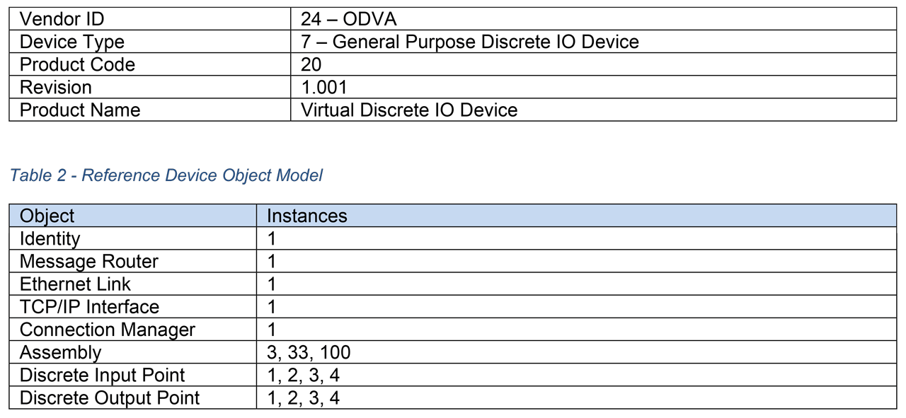
Table 1 – Reference Device Identity. Table 2 – Reference Device Object Model.
Using the proposed CIP Device Description Model and the ODVA xDS Primitives libraries, the reference device is modeled as shown in Figure 8. A System Unit Class library named ODVADemo is the top-level container for the device description. Multiple device descriptions could be created within this container to describe a number of related devices such as a product family. A physical device description with the name “Virtual Discrete IO” is created with the role EtherNetIPDevice. The device Identity information is stored in attributes associated with the EtherNetIPDevice role class.
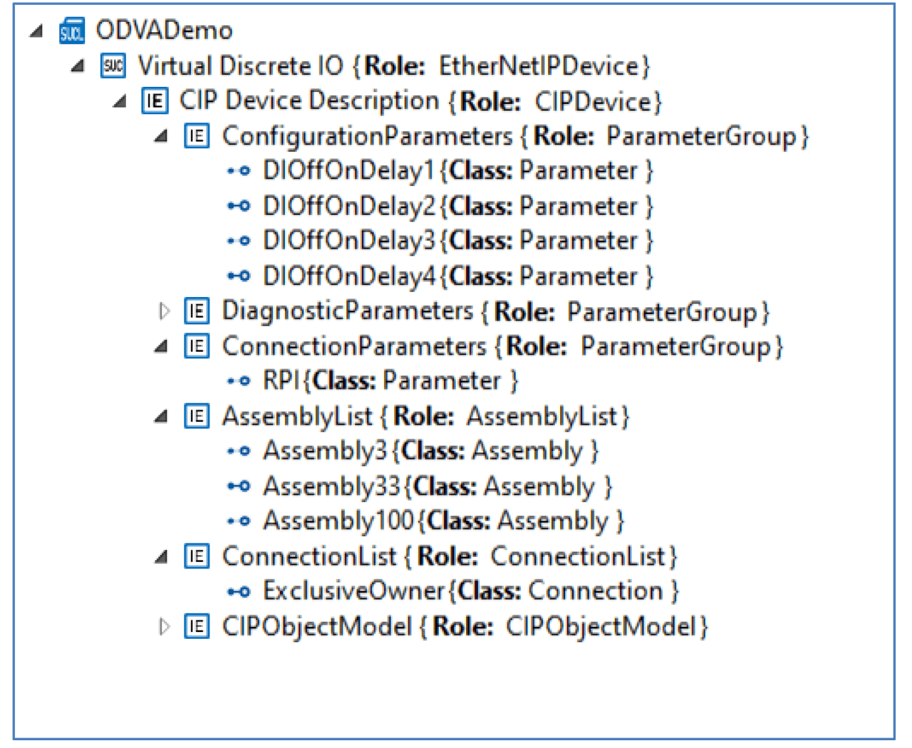
Figure 8 – Reference Device Modeled in AML Using xDS Constructs.
The logical device description is modeled within the element named “CIP Device Description”. This element includes three ParameterGroup containers, one for configuration parameters, one for diagnostic parameters, and one for connection parameters. These groupings can be made in any way the xDS creator sees as helpful.
The AssemblyList contains all published assemblies. Figure 9 shows the layout of the input assembly instance 3. The member list in this example consists of four entries of type AssemblyMember labeled DI1Value, DI2Value, etc. Each of these entries includes a reference to one of the four digital input value parameters defined in the parameter group section. The member list is flexible, allowing various constructs to be referenced and individual bitfields to be defined.
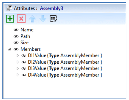
Figure 9 – Assembly Attributes.
In the same way, the ConnectionList contains all the connection definitions. A connection definition contains the standard set of attributes required to define an IO connection as shown in Figure 10.
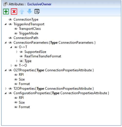
Figure 10 – Connection Attributes.
The design for describing the CIP Object Model section and the Feature List section has not been completed at this time, so our model of the General Purpose Discrete IO device does not include completed entries for those sections. However, this modeling exercise has demonstrated a proof of concept for using this approach.
Use of Open Packaging Conventions to package xDS Components
Along with the device information model which may be represented using AutomationML, there are various additional components which may be needed within the device description. These may include icons and graphics, user manual, Declaration of Conformity, and other vendor-specific files.
There is also the desire to support multiple similar devices of a product family within a single xDS artifact, as well as multiple revisions of the same device. To aggregate these various components into a single, organized, compact artifact, Open Packaging Conventions is used.
The Open Packaging Conventions (OPC) originated out of the Office Open XML file formats for representation of Microsoft Office documents. The OPC specification has been standardized in ISO/IEC 29500-2 [5] and ECMA-376 [6]. The specification provides a framework for structured storage of information within a file which itself is just a “zip” file. The specification allows for the expression of relationships between parts of the file through a directed graph of relationship associations. Additionally, the specification provides a standardized approach for digitally signing the contents or portions of the contents which meets the requirements proposed in the Security Considerations section below.
Implementation details for xDS have not been clarified at this time, but a basic structure using OPC has been proposed which will:
- Allow support for both required and optional sections
- Support future expansion for additional sections
- Support independent digital signing of sections
The support of multiple, independent digital signatures which can be applied to selected sections in the package is a very powerful feature. The SIG envisions two different signatures applied to various portions of the xDS package. Upon completion of developing the xDS, the vendor will apply a signature to the critical, required sections and any other sections desired. Then, upon successfully receiving an ODVA Declaration of Conformity, ODVA will insert the DoC into the package and generate an ODVA signature based on certain critical sections which may not be modified without updating the DoC. Conversely, sections which are not under the ODVA signature could be modified after the fact by the vendor.
The following sections have been proposed:
- File Version: This section will contain specific file version information including creation timestamp, revision number, modification history, and xDS specification version this file conforms to. This content is required to be included in the vendor digital signature.
- Devices: Multiple device descriptions may be included in a single package to represent different devices in a product family, as well as to represent different product revisions of each device. The Devices section will include a listing of all the variations included in this package. Each entry provides a link to the associated AML description of the device, also included in this section. This content is required to be included in both the vendor digital signature and the ODVA signature.
- Graphics: Any graphics images related to the device. A variety of allowable common image formats will be specified. Optional for vendor digital signature; not included in ODVA signature.
- Icons: Icon files used by the devices. Optional for vendor digital signature; not included in ODVA signature.
- Localization: Text in the various languages supported by the vendor, such as help strings is maintained here. This section is required to be signed by the vendor, but not part of the ODVA signature, allowing for corrections or additions to be made by the vendor without requiring recertification by ODVA.
- EDS Files: Vendors may optionally include legacy EDS files in the xDS package for use by systems not supporting xDS device description format. If present, required to be included in vendor digital signature; not included in ODVA signature.
- Vendor Documentation: Optional vendor supplied documentation may be packaged in this section, including manuals or drawings. If present, required to be included in vendor digital signature; not included in ODVA signature.
- Vendor Specific: A location for any optional vendor-specific content. Vendors may choose to encrypt this content. Optional for signature by vendor; not included in ODVA signature.
- ODVA Conformance: As part of the ODVA conformance certification process, ODVA will insert the Declaration of Conformity here. Not allowed for vendor signature; required for ODVA signature.
- Signatures: This section contains all of the digital signature information. This information follows the OPC specification for signatures and complies with the security recommendations in the following section.
Security Considerations
A key aspect for xDS is the concept of a secure device description artifact. A simplified threat model identifies two primary areas of concern for xDS information:
- Invalid xDS device descriptions: This could be accidental or malicious modifications which could cause a tool and/or the device to become a bad actor in the ICS.
- Nonconformant Device: An xDS which misrepresents a device as conformant, allowing it to be incorporated into the ICS, possibly as a bad actor.
There are three primary use cases in which the threat model concerns must be addressed:
Vendor development of the device: During device development, the xDS package will be digitally signed by the vendor to authenticate the source and to prevent modification.
- To be a conformant product, the vendor shall digitally sign the xDS.
- The signature shall be based on a recommended algorithm in NIST FIPS 186-4 or its successors.
- The xDS specification shall define mandatory portions which must be protected by a signature.
- Some portions of the xDS, as well as vendor-specific regions may be included in the signature but are not mandatory.
- Keys used to sign xDS files shall be kept private through a Hardware Security Module (HSM).
Access to the HSM shall be documented. Any access to keys shall generate an audit trail.
ODVA Conformance: Upon successful conformance test, ODVA will insert the Declaration of Conformity document into the xDS and add a digital signature. The signature is tied to both the declaration and the xDS content, providing a secure indication of device conformity.
- Insert the Declaration of Conformity into the xDS of a conformant device.
- Digitally sign the DOC along with other critical components of the xDS.
- Keys used to sign xDS files shall be kept private through a Hardware Security Module (HSM).
- Access to the HSM shall be documented. Any access to keys shall generate an audit trail.
- Maintain and make available a list of trust anchors (root certificate authority) used by vendors for signing their xDS.
End User Tools: End user tools will validate an xDS upon loading. Tools will verify existence of a Declaration of Conformity against the ODVA signature and verify overall xDS content against the vendor signature. Tools must notify the user of any discrepancies. Because there will always be examples in which an unsigned or modified xDS must be used, an override mechanism is recommended. The user must be informed of the security concerns and required to acknowledge this before being allowed to use an unsigned or modified xDS.
- All tools consuming xDS shall verify contents based on the digital signature of the vendor.
- All tools consuming xDS shall verify presence of the ODVA DOC and verify the ODVA signature.
- Tools may provide the ability to bypass verification.
- If verification is bypassed, tools shall provide warning messages to the user before allowing the bypass.
- Signatures shall be validated on first retrieval of a signature. Any subsequent validation should ignore any certificate expiration concerns.
- Tools shall periodically retrieve trust anchor list from ODVA.
Tools to Aid in Adoption of xDS
The SIG recognizes that a large hurdle for vendors will be the lack of established tools. The AutomationML Editor provides a flexible tool for the initial prototyping and validation of xDS concepts but is not an adequate tool for vendors to easily create a complete xDS device description. Therefore, some tools have been proposed and some initial prototyping of these tools has begun.
The first tool is an xDS creation tool. This would be analogous to the current EZ-EDS tool. The intent is to make it as simple as possible for a device vendor to create a device description for their devices. Some of the basic capabilities of this tool include:
- Device Description: Provide a simple hierarchical view to easily create the description. Handle all required AML boilerplate constructs according to the defined CIP device model.
- Packaging: Allow specification of component files from various sources to be added.
- Digital Signatures: Create and validate signatures.
- Conformance: Analyze an xDS for proper required content and format.
The second proposed tool is an xDS library reference implementation. This library would be an opensource reference to demonstrate how tools can read and interpret the information contained in an xDS file.
Summary and Future Work
This article has highlighted the current state of development for xDS by the xDS SIG. This effort will lead to a more robust and secure device description than is currently available. The article has described the use of AutomationML to model CIP devices, the use of Open Packaging Conventions to package the information, security considerations, and proposed tools for adoption of xDS. Going forward, the SIG will be continuing development of xDS toward the publication of the xDS specification and coordinating the development of tools to prove these concepts.