

TechnologyMarch 21, 2022
Power over Ethernet—supply for Ethernet devices via data lines
Learn how Industrial Ethernet devices can use effective cabling for simultaneously transmitting data and for supplying power. Power over Ethernet (PoE) systems are widely used in the industry and will play an important role in the future. Why not use the Ethernet cable for both data transmission and supply?
In process automation systems, important parameters such as temperature, pressure, flow rate, humidity, and many others must be monitored and measured. In the era of Industry 4.0, Ethernet is a popular communication standard. Because Ethernet is wired and transmitters and sensors typically require a power supply, the question arises: why not use the Ethernet cable for both data transmission and supply?
This article describes how Ethernet devices can use the cable simultaneously for transmitting data and for supplying power. Power over Ethernet (PoE) systems are widely used in the industry and will play an important role in the future.

PoE standards
The supply of power via a Cat-5 cable is defined in the IEEE 802.3af Power over Ethernet standard. The PoE standards used to be limited to a few watts, but newer PoE technologies enable even higher power. For example, PoE+ allows power up to 25 W per port and PoE++ (a four-pair Power over Ethernet system) ranges from 70 W to 100 W by using all of the wires of the existing cable. In parallel to this PoE standard, Analog Devices has defined the proprietary standard LTPoE++™, which defines the specifications up to 90 W powered device (PD) power. LTPoE++ reduces the technical complexity of the PoE system in relation to comparable solutions. Plug and play capability, easy implementation, and a safe, robust power supply are further features of LTPoE++.
Moreover, LTPoE++ is interoperable and backward-compatible with the standard PoE specifications of the IEEE. However, the actually usable power is somewhat lower than the specified PD power because of losses in the system as well as cable losses, as is also the case with PoE+ and PoE++.
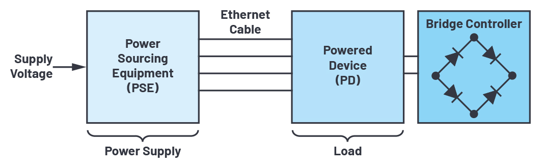
Block diagram showing the main components of a PoE system.
PoE components
Essentially two components are necessary to supply devices over the Ethernet cable: the powered device and the power sourcing equipment (PSE).
The PSE has the task of delivering the power like a power supply, whereas the PD receives the power and uses it (load). PSE devices have a signature process while powering up to protect incompatible devices from damage when they are connected.
This involves first checking the signature resistance of the PD. The PD will only be supplied with power if this value is correct (25 kΩ). If the PSE detects a PD, it starts with the classification; that is, with the determination of the power requirements of the connected device.
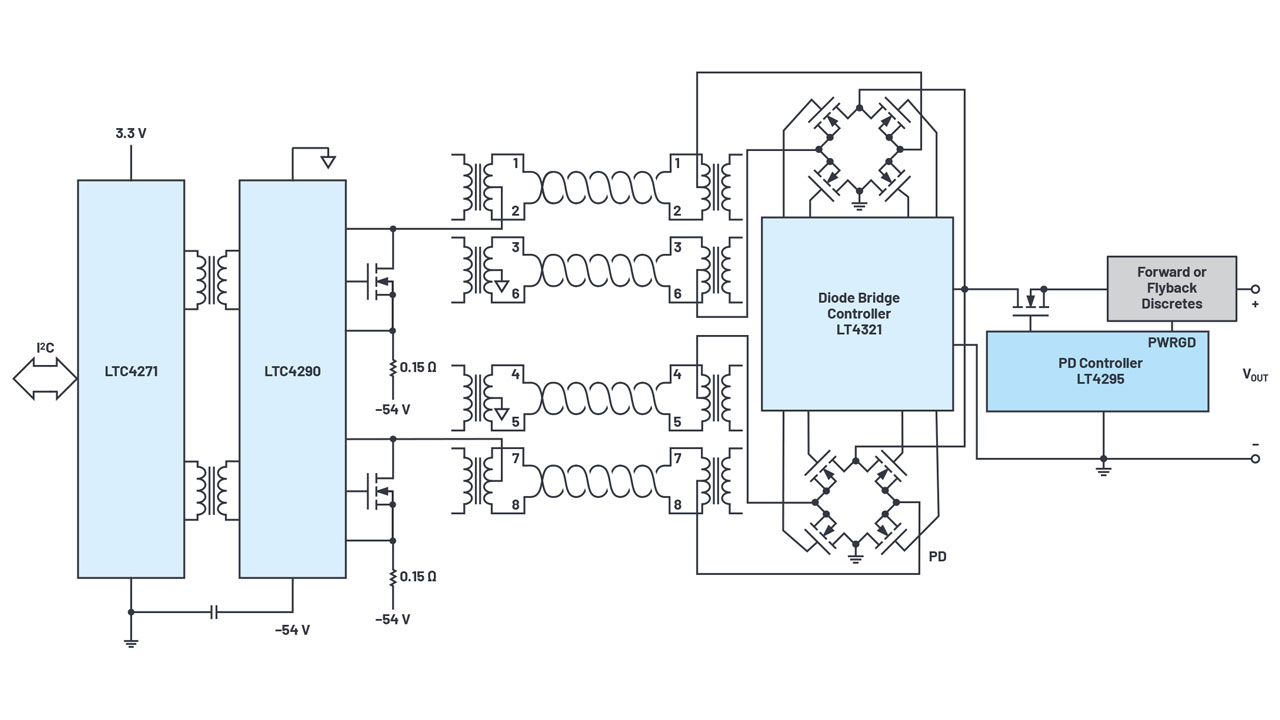
Example of a PoE circuit.
For this, the PSE applies a defined voltage and measures the resulting current. The PD is assigned to a power class on the basis of the current level. The full voltage and current will be supplied if everything is correct. As soon as the PD is supplied, it has the task of converting the PoE voltage of –48 V to a supply voltage suitable for the terminal devices.
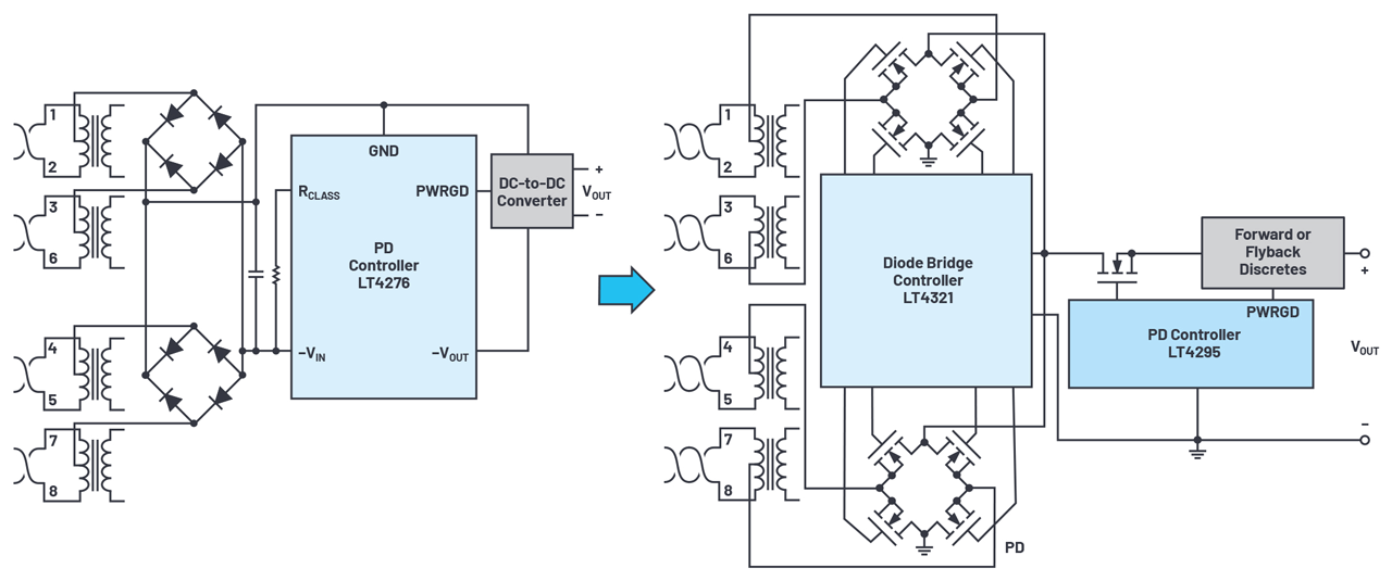
In typical PD designs, an additional dc-to-dc converter (diode bridge controller) is used. It has the task of adjusting or covering the power requirements of the components supplied by the PD. Newer ICs already offer the possibility of integrating the interface and the dc-to-dc converter into a single component for low power classes, which simplifies the design.
Because PDs must accept a dc operating voltage of any polarity over their Ethernet inputs according to the IEEE 802.3 PoE specifications, two diode bridges are required in front of the inputs of the PD. Thus, the PD also works with reverse polarity, regardless of the wire pair used.
PD implementation made easy
With the LT4276 from ADI, an LTPoE++-, PoE+-, and PoE-compliant PD controller with an integrated isolated switching regulator exists. It can be operated both for forward and for flyback topologies, and synchronously for power classes from 2 W to 90 W. Unlike conventional PD controllers of lower power classes, which also have integrated power MOSFETs, the LT4276 offers the option of driving an external MOSFET. Through this, the PD decreases its losses and increases its efficiency.
Because the IEEE 802.3 Ethernet specifications require electrical isolation from the ground connection of the device housing, the LTC4290/LTC4271 isolated controller chipset is suitable as a PSE. The LTC4271 represents the digital interface to the PSE host on the nonisolated side, whereas the LTC4290 offers the Ethernet interface on the isolated side.
The two components are connected by means of a simple Ethernet transmitter. Through this robust PSE chipset design, additional components for generating the isolated power supply can be avoided.
Conventional diode rectification vs. driving via a diode bridge controller.
An increase in the power and efficiency of the overall PoE system can be achieved if the two diodes of the full-bridge rectifier on the PD side are replaced by ideal diodes. Therefore, MOSFETs are used and controlled such that they act like typical diodes.
Through this process, the forward voltage can be drastically lowered due to the low channel resistance (RDS(ON)). With the LT4321 ideal diode bridge controller in combination with the LT4295 PD controller, four MOSFETs can be controlled in a full-bridge configuration.
With PoE, Ethernet devices can be supplied with power at the same time as the actual data transmission takes place via an RJ45 cable. Analog Devices has developed its own proprietary standard, LTPoE++, that supports powers of up to 90 W in parallel to the conventional PoE standards. LTPoE++ offers a robust, end-to-end, high power PoE solution that simplifies the power supply and the design.
The new Chronous™ portfolio is ADI’s portfolio for innovative Industrial Ethernet products. It includes real-time Ethernet switches, PHYs, and protocol processing products, as well as complete network interface products.
The Chronous portfolio was recently expanded with ADI’s release of two new robust Industrial Ethernet PHYs, ADIN1300 (featuring 10 Mbps to 1 Gbps range) and ADIN1200 (featuring 10 Mbps to 100 Mbps range). By combining those new PHYs with ADI’s PoE technology, the Chronous portfolio enables best-in-class, system-level solutions for both power and data.
Thomas Brand, Field Applications Engineer, Analog Devices