

TechnologyJuly 19, 2022
Process Applications Framework using CIP Technologies

Advanced Physical Layer (Ethernet-APL) is gaining attention due to the opportunity it presents to extend the reach of EtherNet/IP into areas in which Ethernet has not been deployed. However, this is just one of several areas where development is taking place to facilitate the use of EtherNet/IP in process applications.
The use of the Ethernet communication technologies has become significantly more prevalent in recent years, with market share data indicating that EtherNet/IP is one of the market leaders. Although EtherNet/IP has been adopted by a broad range of industries, it is recognized that the process industries are an opportunity for growth.
The term “Process” encompasses many different industries, from applications in the Life Sciences, the production of oil & gas, chemical manufacture and the treatment of Water and Wastewater. These industries all have different needs and priorities. These industry sectors in turn will have their own characteristics and requirements. Whilst a skid for producing pharmaceutical reagents may share characteristics with a packaging machine, a refinery is likely to have its own unique requirements. For example, the physical characteristics and size of a refinery or chemical plant is likely to lead to automation components that are separated by long physical distances. This type of application is likely to take additional measures to avoid the risk of explosion.

Regardless of the industry, what differentiates process applications from discrete applications are relatively slow control loops, and update rates between devices that can be on the order of 100’s of ms. The impact of this is that the performance demands on EtherNet/IP target devices is lower than applications in the discrete industries. In contrast, the scale of some process applications means that scanner class devices may have additional demands in terms of the number of connections.
In general terms, although this means that devices developed in the discrete industries can also be deployed in process, the environment in which they are deployed, and specific application needs drive an additional set of requirements that are needed to facilitate the use of EtherNet/IP devices in these industries.
Initiatives such as the Advanced Physical Layer (Ethernet-APL) are gaining significant attention owing to the opportunity it presents to extend the reach of EtherNet/IP into areas in which ethernet has not been deployed previously. However, this is just one of several areas where development is taking place to facilitate the use of EtherNet/IP in process applications.
This article provides an overview of the state of the industry, documenting areas where the state of the CIP and EtherNet/IP technologies are mature enough for adoption and identifying areas where additional effort is needed in order to facilitate the use in real applications.
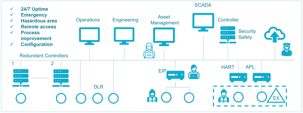
Typical EtherNet/IP process automation network architecture.
Personas
To illustrate how process applications are designed, installed, used, and maintained, we will define a number of Personas:
Cassie: A Control Systems Engineer. Cassie has a background in traditional automation concepts, and has experience with controllers, instrumentation and actuation. She also has experience with fieldbuses such as ControlNet but has had limited direct exposure to IT herself. She is well aware of the need for IT and OT personnel to collaborate – as a prerequisite for delivering the converged architectures needed for contemporary digital manufacturing solutions.
Edward: An Instrument Engineer with responsibility for selecting instrumentation to meet the needs of the process.
Isabelle: An Instrument Technician who has to maintain a broad variety of instruments from a number of different vendors.
Ned: A Network Engineer who spent the first part of his career supporting network infrastructure for a software development company. He chose to move into manufacturing in order to take on a fresh challenge. He has a good understanding of networking as applied in IT but is developing his knowledge of the operations domain.
Sam: A Security Architect. Like Ned, he has a background in IT, but with the increased convergence of IT and OT, he now has responsibility for ensuring that the complete installation follows industry best practices. His job is to ensure that all aspects of the facility are designed in a way that ensure the key requirements of Confidentiality, Integrity and Availability are all met.
Facility Design
Cassie has been tasked to create a process plant network that fulfills the following requirements:
- 24/7 uptime for the highly available part of the process.
- Protection from an emergency event for the critical system operators.
- A hazardous area for both new and legacy devices.
- Remote access to the system for troubleshooting.
- Access to process data for process improvement analytics.
- Simple set up and configuration of instrumentation
Cassie knows about controllers and instrumentation but is not as knowledgeable about network security and topologies, so she elicits the help of two IT professionals from her company – Ned, the Network Engineer and Sam the Security Architect. Cassie has experience with ControlNet, so she turns to other CIP technologies to meet her needs.
To learn more about CIP technologies, Cassie attended a workshop where several of the technologies were described. Cassie learned that device profiles are standardized collections of CIP objects that allows similar device types from different manufacturers to expose control, configuration and diagnostic data the same way. She also learned that the industry has developed a standardized information model, called PA-DIM, to upload data to the cloud. Cassie is very excited to see how these concepts can be used to fulfil her needs.
Architecture
As a starting point for developing their architecture, Cassie, Ned and Sam consider ODVA’s guidelines for EtherNet/IP Network Infrastructure, Cybersecurity, as well as vendor documentation to create a network.
Controller and Device Redundancy
Looking at the details of the specification, the team notes that the application on which they are working on requires a very high level of fault tolerance. The common mechanism by which this is achieved in process industries is through the use of controller redundancy consisting of at least a pair of controllers (primary and secondary). The most crucial applications can require yet more controllers.
The primary controller operates the input/output (I/O), and it executes control logic and communication tasks. Physical I/O and other smart devices are arranged on one or more fieldbus network for access by both processors. In addition, the primary controller must update or mirror itself to the secondary continuously to ensure that I/O status, memory values, and any program changes are shared between the controller pair. This ensures that the secondary controller is ready to assume control seamlessly if needed.
In the event of a major fault—such as a power failure, rack fault, or processor error the primary controller switches over to the secondary, which should seamlessly continue with operation without any LOC (Loss of Control) or LOV (Loss of View). This action is known as switchover or failover.
Cassie notes that at present, controller vendors have proprietary mechanisms implemented with CIP devices to ensure there is no LOV or LOC during switchover/failover. Techniques used include the use of IP address switching, Gratuitous ARP (GARP) and hold/freeze of process values. With this approach, there is potential for unexpected results as device vendors are not following a standardized mechanism for achieving the switchover from primary to secondary. Furthermore, she notes that some of the devices she wishes to use within her architecture do not support GARP, and therefore a connection loss is experienced when control switches from primary to secondary.
These observations suggest that although redundancy solutions are available, there is a need to standardize the Redundancy and Controller failover/switchover scheme to have seamless integration of CIP devices in process industries – and to achieve full application coverage.
High Availability and Media Redundancy
In line with many process applications, the specification with which Cassie is working with calls for high availability – defined as the ability for the system to tolerate a single failure. Looking initially at the media, Ned notes that a number of options are possible – for example the Rapid Spanning Tree Protocol (RSTP). Cassie points out that although this might work for the connection to the SCADA and the broader plant, the convergence speed of this standard protocol is not sufficient for maintaining a connection between a controller and a device.
Based on this feedback, Ned chooses to implement the Device Level Ring (DLR) protocol. The DLR protocol provides the means to detect, manage, and recover from single faults in a ring-based network. It is intended primarily for implementation in EtherNet/IP end devices that have multiple Ethernet ports and embedded switch technology and allows applications requiring media redundancy to be realized. The protocol provides for fast network fault detection and reconfiguration to support the most demanding control applications. Cassie agrees this is a sufficient approach since the instrument technician staff is readily available to replace any failed device.
One of the ways in which this is achieved is through the use of a protocol such as the Parallel Redundancy Protocol (PRP). From Cassie’s experience, she knows that this works well with EtherNet/IP devices because the media redundancy protocol works completely independently of the application.
However, she notes that in many cases, the devices that she wishes to use do not support PRP natively, and that switches with Redundancy Box (RedBox) capabilities are needed to realize the architecture. She feels that being able to purchase more devices with native PRP support would simplify her architectures
Long Cable Runs and Connectivity to Hazardous Areas
Cassie notes that as per the requirements of the facility and there are some parts that need to be located more than 100m from the nearest ethernet switch. Cassie also has to install devices within a hazardous area. Whilst fiber optic cables can be used for the network infrastructure, this cannot be used for connecting to instruments directly as it would require separate distribution cabling to provide power to the devices.
Cassie knows that not every device or switch can be installed in a hazardous area, so she and Ned work together to create a network solution that complies with hazardous area approvals. Cassie finds existing devices that support 4-20mA HART® protocol – in which the transmitters are powered by the control loop. They also identify newly introduced devices that support Ethernet-APL in which the power for the instrument is supplied over the network.
They note the simplicity in using this technology owing to the ability to use existing two-core cable that is already present in the facility. They also note that functionally, EtherNet/IP instruments for Ethernet-APL are identical to other EtherNet/IP instruments. They see that this presents an opportunity to collect information from devices from which the level of diagnostic information had been limited to either a standard analog loop or to what was available over HART – noting also that the move from HART to EtherNet/IP also provided a much faster update rate.
From a network architecture perspective, Ned explains that standard industrial Ethernet switches cannot be used for either type of devices so Cassie and Ned research the types of switches needed and realizes a HART translator is needed to communicate with the 4-20mA HART devices and an Ethernet-APL switch is needed to integrate the Ethernet-APL devices.
They conclude that Ethernet-APL is a advanced technology that has an opportunity to significantly enhance the information available regarding the performance of their facility.
Connecting to Legacy Technologies
Cassie is told by her management that part of the installation will make use of a skid that will be transferred from another facility. As she investigates the specifications of this skid, she realizes that it is 20 years old. From her history in the industry, she expects that it might have some ethernet connectivity, but that its capability is likely to be limited. Her expectation is that the instrumentation is likely to be using 4-20mA HART.
Isabelle and Cassie have long recognized the difficulty in using HART instrumentation. Process maintenance teams have long been challenged with gaining access and connectivity to service their lowest-level field devices. Traditionally, plant personnel needed to walk out to the processing area and use a handheld communicator or web server to connect to each device individually – a process that can take hours. This, together with the need for better real-time information on the performance of devices has driven a desire for better EtherNet/IP device connectivity.
Although Cassie would like the skid to be upgraded to use EtherNet/IP instrumentation, her management tells her that she has a limited budget for the integration of the skid. Furthermore, she notes that some of the more specialized devices on the skid do not have an EtherNet/IP equivalent on the market. She notes however that the EtherNet/IP Specification from ODVA defines a standard mechanism for integrating HART devices into the Common Industrial Protocol (CIP). Using this mechanism, a CIP originator (such as an industrial control system) can communicate with a HART device as if it is a native CIP device. The result is seamless communication between CIP-based devices and HART-based devices, without needing any changes to the HART devices or the CIP originators: from the CIP originator’s perspective, the HART device appears as a CIP target device, with CIP objects and with CIP communication mechanisms. However, from the HART device’s perspective, all HART commands originate from the Translator in the form of standard HART commands.
In summary, Cassie notes that the ability to use a HART to CIP translator meets the immediate need for integrating HART devices into a CIP architecture.
Meeting Safety Requirements
Safety in process can mean different things depending on the specific industry. The chemical, oil and gas industries all aim to avoid the release of hazardous or explosive substances into the environment. Like the discrete industries, all facilities have a goal of protecting their employees from injury or death.
In the case of the facility being designed by Cassie, the safety specification calls for the use of Safety Instrumented Systems (SIS) as defined by the IEC61511 standard, which covers the application of electrical, electronic and programmable electronic equipment in the process industries.
This requires the components of the system to meet a Safety Integrity Level (SIL) rating. The complete application also has to have a SIL rating. This calculation is based on the ratings for the complete process loop, covering the sensors, control logic and actuators. Cassie is aware that the IEC61511 standard references the IEC61508 for the design of safety components.
She is also aware of the CIP Safety standard. In studying the CIP Safety standard, she sees that it has some useful characteristics: it ensures that the behavior of components in the event of a failure is well defined. She sees that the features of the protocol provides the means to protect against faults arising for the corruption of data, unintended repetition, incorrect sequence, loss of data, unacceptable delays, insertion, masquerading and addressing faults. Cassie notes that it operates at the application layer and uses the black channel principle, meaning that only the end nodes need to be safety certified and that that there is no need to certify the intermediate networking hardware – something which will no doubt be of interest to Ned, the Network Engineer.
However, she struggles to find any guidelines to help her use CIP Safety certified devices in applications that need to be built according to the 61511 standard. She also notes that offerings from vendors are often segmented, with specialized safety solutions being sold as a separate offer to standard DCS systems. She decides to engage a specialized process safety contractor to help her meet the needs of her application.
Security
The specification to which Cassie and Sam are working calls for them to follow industry best-practice for ensuring that their facility is well protected. They have three key goals: to ensure that company assets (recipes and other confidential information) are not compromised, that the integrity of the operation is not impacted, and that production can continue 24 hours a day, 7 days a week. At the same time, they have a requirement for real-time sharing of production information with management elsewhere in the world, and they also need remote access to facilitate maintenance by global suppliers. This need rules out an air-gap system.
Sam is aware that the industry standard for securing OT systems is IEC62443. Like Safety, this defines a number of security levels and they believe that Security Level (SL) 3 – the provision of protection against intentional misuse by sophisticated means with moderate resources, IACS-specific knowledge and moderate motivation is a realistic target.
Sam notes that two parts of the standard are most relevant. The 62443-3 standard applies to their installation as users, and the 62443-4 standard applies to the devices that they deploy within the facility. Cassie is also aware of the existence of CIP Security™ – which allows the communication between devices to be secured. They note that there appears to be alignment between the needs of the standard and the capabilities of the devices. Overall, Sam and Cassie feel that as with safety, further guidance is needed to help them navigate the complexity of meeting 62443 certification and in understanding how ODVA technology can help them to achieve this.
Commissioning and Integration
Aside from the architecture, Cassie and Edward are aware of the time it takes for the team to commission and integrate devices into the control system and are looking for ways to simplify and speed up the activity. They note that EtherNet/IP devices are coming on to the market with standardized device profiles. They see these profiles as a way for her programmers to further standardize their interface modules – and allowing the team to concentrate on developing and implementing their core control loops and visualization concept.
Device Configuration & Management
Edward, the instrumentation engineer recognizes that this is an installation with a large number of instruments supplied by a number of different vendors. He has extensive experience using Asset Management solutions to configure instruments and uses the software tools to create backups of the configurations in each device.
Edward works with Isabelle to ensure that all the instruments in the installation are configured correctly and the backup configurations are maintained. However, when Isabelle replaces an instrument, she does not want to have to walk to an Engineering Workstation to restore a configuration. Having spent many years maintaining devices, she prefers to use the front panel of the instrument.
She has a paper notebook where she writes down the parameter settings from the failed instrument (if she can) and after replacing the instrument she enters the parameters from the old instrument into the replacement unit. Her experience has meant that she has a sense for what the parameter settings in an instrument might be, but she does not have the full insight into the functionality of the process held by her colleagues Cassie and Edward.
As they investigate the capabilities of CIP devices, they see that mechanisms exist to facilitate the integration of EtherNet/IP instrumentation into their DCS. However, they are surprised to see that different manufacturers have interpreted the requirements in different ways. Consequently, they find that some devices cannot be added to the control system at all. Other devices can be added but lack the capability to be configured over the network. A third class of instrument can be added and configured but there is little standardization between the interfaces.
They are also surprised to see that there is no equivalent to the Asset Management Software used by Edward – although they do see that their existing tools can be used over the EtherNet/IP backbone network – and that it has been recognized that a solution based on combining EtherNet/IP with other standards such as FDI can help deliver strong benefits to the user community.
Although they are aware that some DCS suppliers offer some interesting capabilities in terms of device configuration (and in some cases, for device replacement), and they are aware of ODVA’s xDS initiative, they note that this latter solution is not yet complete and opt to remain with their existing asset management software owing to the lack of standardization that exists across the devices they wish to use.
Device Maintenance in Use
In her role as instrument technician, Isabelle has to maintain the functional state of the process. Inevitably, devices fail in operation and Isabelle has to replace them.
Her life is made easier when the instruments can report potential problems in advance of failure. Given that she has to support a range of instruments, her work is made easier when problems are reported in the same way. She is tired of every manufacturer designing instruments to report issues using proprietary definitions.
Isabelle airs her grievances to Cassie, and Cassie notes that ODVA has recently published the Process Device Diagnostics object, which is based on the NAMUR NE 107 standard. When instruments implement the Process Device Diagnostics object, the instruments provide Isabelle with a standardized way of reporting instrumentation malfunctions and an indication if a process is operating out of specification. Isabelle can easily see which error reports are failures and need to be acted on immediately and which are less critical and can wait for action.
Isabelle is especially happy when Edward, the Instrumentation Engineer, specifies instruments with the Process Device Diagnostics object implemented. Now all Isabelle needs to do is convince Edward to specify devices that can perform predictive maintenance.
If she had techniques to help determine the condition of the instruments in order to estimate when maintenance should be performed, she would not have to make so many late-night calls due to failed instruments. Her maintenance activities would become much more predictable and she would not waste the company’s money on performing tasks that were not warranted.
The team notes that the functionality they need is available in a limited range of devices to date and that their needs will be best met when more manufacturers choose to implement the Process Diagnostics Object.
Device Replacement & Interchangeability
Although Isabelle makes her best efforts to maintain instruments to the best of her abilities and to address potential problems during scheduled downtime, inevitably, there are times when devices do fail during production. Oddly, failures often occur when the facility is operating with a reduced staff – for example at night or during the weekend.
Naturally, it is imperative for users to be able to replace failed equipment quickly in order to return to production.
Having worked in different industries, he notes that there are different perspectives on how this scenario should be managed. Owing to regulatory compliance, a life science application will require a failed device to be replaced with an identical unit to align with what has been validated by the relevant regulatory authority. In contrast other process applications do not require the same level of regulatory compliance.
For this scenario, Edward recognizes that the primary need is to allow the on-site maintenance staff to be able to use whatever instrument is available in stores, without having to worry about the manufacturer or backwards compatibility with the firmware version. For example, a pressure transmitter manufactured by Company A fails in the facility, but the maintenance store only has a pressure transmitter manufactured by Company B on the shelf. Edward notes that ODVA is working on a series of device profiles to standardize the data definition within EtherNet/IP instruments.
ODVA recognizes that the user is looking for the ability to work with “whatever works” – in other words, the ability to use an instrument or actuator from any vendor and for it to be integrated into a Control System without anyone having to make any changes to the program controlling the application. The Coriolis Flow profile is an example of the type of definition that is needed in order to facilitate this use-case. Edward notes that the profile standardizes the configuration parameters across similar measurement devices – which Isabelle’s commissioning time more efficient.
Overall, Edward and Isabelle note that ODVA offers the capability they need; however, as with maintenance, their ability to use it is limited by the class of device in which it is available as well as the number of devices supporting it.
Compute and Cloud Connectivity
One of the strategic goals that Cassie needs to meet is for continuous process improvement. She is aware that data from the operations needs to be collected for analysis, and that this can be done using compute capabilities either on-site or off-site. She is aware that OPC-UA is becoming a standard that is gaining significant traction for cloud connectivity, and also that work has been done on mapping CIP objects onto an OPC UA Information Model.
Further investigation reveals that a Device Information Model for representing Process Devices has been published. She also aware that ODVA has documented the Use-cases for a CIP Companion Specification for OPC UA and confirms that these are in line with the requirements of her facility. She is also pleased to see that there is alignment between the device profiles and the PA-DIM standard.
Overall, she concludes that her needs are well understood and the infrastructure she is selecting will deliver the connectivity she requires, however she also notes that products based on these concepts are not yet available.
Summary
In summary, the process plant network that Cassie was tasked to create had several diverse requirements and Cassie and her team was able to fulfill them by using ethernet as a backbone and CIP technologies where appropriate. They conclude that the state of ODVA technologies allows them to realize the architecture of their operations in the way they see fit.
Conclusion
In conclusion, it is clear that many aspects of a process application can be achieved using ODVA technology today. The fundamental function of exchanging information between sensors, controllers and actuators can be achieved using EtherNet/IP. Features exist that facilitate high availability topologies, full system redundancy, deployment of devices over long distances, installation of equipment in hazardous environments – all with a feature set that aligns with industry best practices. In addition, the integration of older technologies into a CIP based architecture can be achieved with ease. In use, there are means by which diagnostic information can be presented in a standardized way and there is a move towards facilitating the exchange of devices without having to make changes to the control application.
There are however some areas where more work is needed, specifically in terms of providing guidance on achieving process safety, further clarity regarding the use of CIP Security to meet industry standards, defining a standard way for managing redundancy and in enhancing the way in which EtherNet/IP devices are configured and managed.