

TechnologyMarch 22, 2024
Process Device Profiles come to life in multi-vendor environment

This article highlights how Process Device Profiles can be utilized in a multi-vendor environment. The focus is on a use-case in which an operator is informed of an error, and able to take action, leading to resolution of the problem through replacement of the instrument with an alternative from another supplier.
The value of EtherNet/IP in the process industries is well recognized and is also a recommended Ethernet-based standard that is specified in NAMUR NE168 in 2018. However, adoption has faced a number of challenges.
A review of the state of the art was conducted in 2021 and identified areas such as the standardization of diagnostics, the ability to deploy instrumentation in hazardous environments, the need for long cables and the integration of legacy HART-based instrumentation into EtherNet/IP installations. Since then, some of these challenges have been addressed with vendors starting to bring new functionality to the market.
This article highlights how recently published functionality has been realized in a multi-vendor environment. The focus is on a use-case in which an operator is informed of an error and able to take action, leading to resolution of the problem through replacement of the instrument with an alternative from another supplier.
Real-life scenario in a process plant
Isabelle works in a large plant experiencing the industry-wide shortage of skilled technicians. Edward, the instrumentation engineer, tries to have multiple sources of instrument suppliers for each device technology (Flow, Pressure, Temperature, Level) to keep the process running if a problem arises. This creates a lot of extra work for Cassie, the control engineer, for device integration and configuration.
Friday, June 30th a nice summer day, Isabelle is starting her work after a shift change at the tank farm. Everything points to a pleasant working day before the upcoming long weekend. Suddenly the calm is broken by an annoying alarm, indicating that one of the flowmeters at tank 13 has stopped measuring. Diagnostic information on the Asset Management display shows that measuring hasn’t stopped due to missing flow but due to a flowmeter malfunction. To get more information about the root cause of the problem, Isabelle asks Edward, the instrument engineer, to look at the faulty flowmeter.
Edward determines that something has crashed into the flowmeter’s transmitter, the component of the flowmeter which is in charge of the communication. Fortunately, the pipe has not been damaged so the oil is still flowing into the tank and not onto the ground, but the flowmeter has to be replaced. Edward informs Isabelle about the situation and asks her if she can get a new device from stock for the exchange. Looking at the stock inventory list, Isabelle finds out that there is one flowmeter left but its vendor is different from the damaged one. Fortunately, it has the same device dimensions and should fit.
This story has two versions, one without the Process flow device profile (which is presented first) and the other with a Process flow device profile (which follows after the first).
Without the Process Flow Device Profile
A call to the vendor of the damaged device shows that due to the upcoming long weekend, a replacement device cannot be delivered before the end of next week. Since the tank farm is massively dependent on tank 13, the damaged device must be replaced as quickly as possible. Therefore, Isabelle removes the damaged device and replaces it with the one from stock.
After Isabelle has finished replacing the device and made the device connections correctly, the controller was not able to receive measurement data, because the data assemblies are completely different from the former, damaged device. For this reason, the program within the controller must be adapted to the communication structure of the new device.
Isabelle calls Cassie, the Control Engineer, to inform her about the situation and to ask her to reprogram the controller. Cassie is understandably upset, but if she doesn’t follow Isabelle’s request, the tank farm would have to be taken offline for the long weekend. This would result in financial loss and angry management so there is no alternative solution; Cassie must interrupt her long weekend break to get the plant producing again.
With the Process Flow Device Profile
Isabelle had such a situation years ago and she remembers that replacing a device by one of a different vendor resulted in lots of problems reprogramming the controller. In addition, Cassie is the only one who can change the control program and she has already left for her long weekend tour.
But wait! Last year Isabelle had an invitation to the ODVA Annual Meeting and she remembers that in a presentation someone introduced the Process Device Profiles. That means, two devices from different vendors supporting the same Process Device Profile may be interchanged without the need of adapting the control program. From the controller’s point of view, nothing has to be modified.
Cassie showed Isabelle how to do this some time ago and it is quite easy. Hoping that the two devices support the same Process Device Profile, she has a look at the device’s data sheets. Fortunately, both devices support the ODVA-defined Flow Profile, so Isabelle removes the damaged device and replaces it with the one from stock.
Even though the presenters from the ODVA meeting last year were totally convinced that replacing one profile device by another is quite easy, Isabelle is skeptical. Isabelle starts some standard systems tests that check the consistency of the plant’s control program. And voilà: Each of the test pass; the measurement values and the status are visually verified.
The story on the right side was showing that the Process Device Profiles are working, and they delivered what was promised: easily replacing one device with another of a different vendor supporting the same Process Device Profile. It saved a lot of money and more importantly: No one was angry due to emergency operations during personal time.
More than just another technical improvement, this story shows that devices with Process Device Profiles also reduce stress in daily activities in the process industry.
Prerequisites for ease-of-use
Prior to the availability of networking technologies, connecting instrumentation to a control system was straightforward. The extensive use of 4-20mA transducers, and a single process value from an instrument made it very easy to connect devices. Once configured, exchanging a device was very straightforward.
Whilst flexible, 4-20mA signals connected through I/O modules have limitations. Today’s more advanced field devices include many diagnostic capabilities, error-reporting and a multitude of variables that can be used in more complex applications. However, each device works in its own way, making an exchange very difficult. Engineering effort is needed to add or configure the replacement instrument in a fault scenario.
The need for Standardization is therefore clear and needs to address the following areas:
- Commissioning
- Data exchange
- Diagnostics
- Compute Connectivity
- Support
The NAMUR NE 131 standard addresses some of these areas, and it follows that an instrument on EtherNet/IP should also follow this standard.
Commissioning
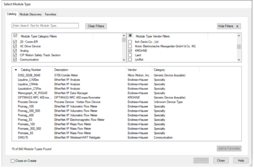
Figure 1: Device Selection in Logix Designer.
Prior to the definition of Process Device profiles, DCS systems typically offered configuration methods that were based on selecting the vendor of a device based on the presence of an EDS file, custom code, or other configuration mechanism such as a DTM or FDI package.
Figure 1 highlights the challenge of selecting a process instrument. Whilst it is clear that there is a mechanism for achieving connectivity, it remains heavily vendor dependent. Devices of the same class have different names and characteristics and it is not clear whether these devices are similar – nor can one identify the differences. In addition, the functions that are visible in the DCS are a result of what has been presented by the device vendor, or which is exposed by the supplier of the DCS. As a consequence, every device looks different, complicating the configuration process. Furthermore, it limits the ability to exchange a device with one from another vendor.
Data exchange
After selecting a device, the DCS creates input, output and configuration data structures based on how the DCS vendor chooses to present the data. In some cases, this is taking a structure that is provided in the EDS file and creating tags that are in line with the information that has been provided in the EDS.
In other cases, this is achieved using custom code. Regardless of the mechanism used, the tag structures that are created are not consistent between vendors. Different devices will have different tag structures, making it difficult to identify the information needed. This in turn can make it challenging to identify the information needed for diagnostic purposes.
Configuring devices that do not have a pre-defined or standardized interface can also be difficult. Some device vendors may choose not to implement an EtherNet/IP Configuration Assembly. Other vendors may opt for their own design. In both cases, this adds an additional burden on the user who has to understand how to configure multiple devices by studying documentation and then to implement a configuration schema to meet the needs of their plant strategy.
Diagnostics
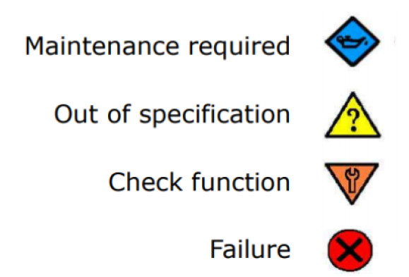
Figure 2: NE107 Icons.
A standardized method to ensure that device diagnostics are easily accessible, understood, and easy to monitor is desirable. The simple traffic light system is used in the NAMUR NE107 standard to indicate the status of a device and aims to draw the attention of an operator when required. With the NE107 recommendations having broad adoption and acceptance across the industry, it makes sense for a process instrument on EtherNet/IP to align with this standard.
Compute connectivity
A broadly accepted standard for interfacing devices to PC’s, servers and the cloud is OPC-UA. This includes the support for data models and defines a wide range of companion specifications for achieving connectivity to a wide range of applications. The data model of interest to the Process industries is the PA-DIM model. It follows that any EtherNet/IP device that wishes to provide information outside the DCS should include the ability to align with the constructs defined in this standard.
Support
The variability that exists in terms of configuring and setting up devices today means that support personnel have to have awareness of multiple techniques for diagnosing and solving problems. This scenario exists not just with CIP devices, but also with legacy technologies such as HART, Profibus and Foundation Fieldbus. A Process device profile therefore can simplify the learning process for a maintenance technician because he will have to learn and understand the capabilities of just one profile per class of device.
Process Device Profile to the rescue
The Process Device Profiles are a collection of CIP objects to standardize the data and services provided for a process measurement. To date, Process Device Profiles have been published for Coriolis Flow, Electromagnetic Flow, Vortex Flow, Standard Pressure and Scaled Pressure. Figure 1 is an example object model for a Process Device Profile and will be described in the following paragraphs.
To support Process device profiles, two new objects were introduced in the April 2023 CIP specification:
The Process Measurement Value Object (Class Code 0x112) contains the measurement values and status along with common configuration attributes such as engineering units, damping, cutoff and zero point. The Process Measurement Value Object also allows for the measurement values and status to be simulated. All Process Device Profiles will contain at least one instance of a Process Measurement Value Object.
The Process Totalized Value Object (Class Code 0x113) is a companion object that is associated with a Process Measurement Value instance and accumulates that measurement value to report it as a total. The Process Totalized Value Object also provides attributes to start, stop and reset the totalized value. Not all Process Device Profiles will contain an instance of a Process Totalized Value Object.
Each Process Device Profile specifies which measurement and totalizer instances are to be supported and what data is to be included in the input, output, and configuration assemblies. Because the CIP Spec has created separate assembly number ranges for profile specific assemblies (ID 1-99) and vendor specific assemblies (ID 100 – 199), there is no danger in the profile and vendor assembly numbers to conflict with each other.
Each Process Device Profile also specifies which instances of the previously published Process Device Diagnostics Object (Class Code 0x108) are to be supported. The supported instances were obtained from the NE 107 guidelines. An improvement was made to the Process Device Diagnostics Object in the April 2023 CIP specification that allows for the diagnostic instances to be simulated.
Each Process Device Profile specifies which Identity Object attributes are required to be supported to ensure alignment with the device representation in PA-DIM. The Process Measurement Value Object and the Process Totalized Value Object were also designed to be compatible with PA-DIM.
Each Process Device Profile may contain the File Object so that an end user can download the supported EDS file(s) from the device.
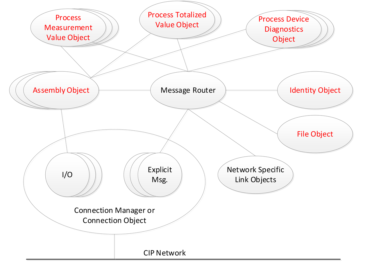
Figure 3 – Example Process Device Profile Object Model.
Device interchangeability
To achieve device interchangeability between vendors with ease of use in mind, a new Profile Vendor ID (0xFFFB) was introduced. A device that implements a Process Device Profile will accept a Forward_Open service targeting the Profile Vendor ID or the manufacturer’s Vendor ID. This segregation of the two vendor IDs allows for the implementation of profile specific EDS files that are maintained by ODVA and makes it clear to the end user that their system is only using profile specific features. This gives the end user confidence that devices of the same profile can be interchanged.
With the addition of the new objects and Process Device Profiles, users can easily interchange devices from different vendors and controller manufacturers can assist with the ease of use.
Conclusion – “pièce de résistance”
The definition of profile-based connection mechanisms simplifies the experience of the end-user. At system design time, they can now choose an ODVA profile that provides standard connections and diagnostics, or a vendor-defined implementation that allows additional capability specific to a vendor’s device.
All Profile EDS files will use the Profile Vendor ID. They will be created and maintained by ODVA in the Process Industries SIG and should not be modified by vendors or users.
Both end users and vendors of controllers can benefit from the approach outlined in this paper. User application logic should be easily re-usable, due to the use of identical data assemblies for each vendor’s device. Additionally, DCS/PLC suppliers can develop and provide to customers one set of user interfaces, such as for device configuration and HMI faceplates. These features will drastically reduce the time required by Control Systems Engineer Cassie during the system development phase.
Dawn Kelsch, Emerson; Michaël Voegel, Endress + Hauser Digital Solutions; E Rizwan Mohammed, Honeywell; Winfried Ernst and Carsten Fuchs, KROHNE; Arnold Offner, Phoenix Contact; Carl Schumaker and Vivek Hajarnavis, Rockwell Automation