TechnologyNovember 7, 2004
Looking behind Industrial Ethernet protocols

Ethernet is an incredibly versatile network medium offering bulk data carriage for automation and process control applications. But it is not a protocol in its own right. To do anything useful it requires an agreed format impressed on the data stream - the Industrial Ethernet protocol - understood by the system application layer which it serves.
Having conquered the office automation world, Ethernet and TCP/IP is now driving a transition from centralised to distributed control systems by promising seamless communication within the automation and Enterprise pyramid. Meeting conditions on the factory floor has required adaptation, particularly regarding requirements for real-time behaviour. Non-deterministic communication protocols such as HTTP and FTP provide a useful start, but the creation of additional Ethernet-friendly application protocols fulfilling industrial requirements has proved to be necessary.
OSI Reference Model
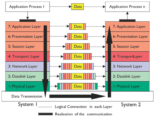
The OSI reference model schematically describes and standardises the communication between devices in a network architecture. Functions necessary for communication subdivide into seven function layers. Each respective lower layer provides its services to the layer above via well-defined interfaces.
Before user data (Application Process) can be sent over the Ethernet medium, it has to be passed down through the protocol stack from upper to lower layers eventually to be embedded in frames of the particular lower layer (encapsulation). After a data packet is sent over the lowest (physical medium) layer, the data it contains passes upwards through all the higher layers at the receiver device until it reaches the application layer. The whole process requires a logical interaction within each layer to complete the network connection.
Ethernet realises layers 1 and 2 of the OSI reference model in a manor specified by the IEEE 802.1-3 standard.

Data exchange in the OSI Reference Model
The upper lying layers implement Internet Protocol IP (Layer 3) and the TCP and UDP (Layer 4) transport protocols. Layers 5 to 7 provide application protocols such as FTP, telnet, SMTP, SNMP as well as protocols for specific applications as required by the control applications. However, these automation protocols can also replace or extend layers 3 and 4 (IP and TCP/UDP) in some applications.
Layer 1 represents an insecure, bit by bit data transmission via a physical medium. Regarding standard IEEE 802.3, an Ethernet frame has the following format:
| Preamble | Destination | Source | Type Field | Data Field | Check |
| 8 Byte | 6 Byte | 6 Byte | 2 Byte | 46-1500 B. | 4 Byte |
| Preamble | Used for synchronisation of the receiver and indicates the start of the Ethernet frame |
| Destination | Receiver address |
| Source | Source address |
| Type Field | Type of higher layer protocol (eg.TCP/IP) |
| Data Field | Contains the data transferred from the source station to the destination station. |
| Check | Contains Cyclical Redundancy Check (CRC) value used for error checking. |
Organisation of a standard Ethernet frame
Layer 2 adds reliability to the physical layer transmission by ordering the data into frames and adding error checking and addressing information. It also provides access to the networking media for control of access rights. The access to the physical transmission medium is controlled via the access mechanism CSMA/CD, as specified in IEEE 802.3. With this mechanism it is possible that two or more stations start a transmission and then detect a carrier from another station. All stations within the network share Ethernet (Shared Ethernet) for data transmission by this method. By contrast, application of Switched Ethernet technology results in avoidance of data collisions so removing the system slowdown produced by the CSMA/CD access method allows Ethernet to work in duplex mode.
Layer 3 implements Internet Protocol (IP) to manage routing of datagrams from one network to another. Outbound data is passed down from the Transport Layer, encapsulated in the Network Layer’s protocol, and then sent to the Datalink Layer for segmentation and transmission. Inbound data is de-fragmented in the correct order, the IP headers removed and then the assembled datagram is passed to the Transport Layer. Currently, the IP in version 4 (IPv4) with an address range of 32 bit is used. IPv6 which is now coming into service enlarges the address range to 128 bits.
Layer 4 is responsible for an error-free and sequence-compatible transmission of data. Within this layer, TCP (Transmission Control Protocol) and UDP (User Datagram Protocol) stacks are implemented. TCP is a connection based protocol designed for ping-pong style errorfree transport of data with large packet sizes. On the other hand, UDP is a one way protocol. Transmission via UDP is faster and the protocol size is smaller than TCP, but errors will not be fixed. UDP is especially suitable for fast and cyclic data transfer.

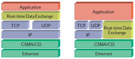
Real-Time architecture within the OSI Reference Model
The interpretation of transferred data is user related and specified in application protocols (Layers 5-7). In the office world a wide range of application protocols, known as IT standards, are available, e.g. FTP, HTTP, etc. Industrial communication with protocols incompatible to each other use these layers. These automation protocols can be realised in different ways. Either the automation protocol is directly mounted on Layer 4 of the OSI reference model (Modbus/TCP, EtherNet/IP and CIPsync, JetSync) or, additionally, Layer 3 and 4 will be replaced and extended (ETHERNET Powerlink, PROFInet, SERCOS).
EtherCAT
EtherCAT (Ethernet for Control Automation Technology) is an Ethernet-based automation concept developed by the German company Beckhoff. In this technology the Ethernet packet is no longer received, then interpreted and copied as process data at each module within the network. Instead, the Ethernet frame is processed on the fly: For each module within the network, data addressed to that module is read, while the telegram is forwarded on to the next module. Similarly, input data is inserted while the telegram passes through. The telegrams are only delayed by a few nanoseconds so increasing performance of the system towards real-time behaviour. The last module within the network segment sends the frame back to create a logical and physical ring structure. All transferred data comprises fully compatible Ethernet frames; each module converts these Ethernet frames to what is effectively an internal fieldbus.
The real-time Ethernet frames have priority over other data (such as those required for configuration or diagnosis, etc) via an internal prioritisation system. Configuration data is transmitted in the time gaps if sufficient time is available or by using a specific service channel. Fully maintained Ethernet functionality of the operating system achieves compatibility with conventional IP protocols. Synchronisation mechanisms based on IEEE 1588 achieve performance capable of supporting motion control applications under EtherCAT.
EtherNet/IP
EtherNet/IP, based on Ethernet TCP or UDP IP, is a stack extension for automation industry communication. The ‘IP’, in EtherNet/IP, stands for Industrial Protocol. EtherNet/IP was introduced by the ODVA towards the end of 2000. In EtherNet/IP the upper-level Control and Information Protocol (CIP) which is already used in ControlNet and DeviceNet is adapted to Ethernet TCP/IP and UDP/IP respectively.
The specification of EtherNet/IP is public and free of charge. In addition to typical office applications like HTTP, FTP, SMTP and SNMP, EtherNet/IP provides a Producer/Consumer service allowing the transmission of time-critical messages between control device and I/O devices. Secure data transmission of non cyclic messages (program up/download, configuration) will be realised using TCP and time-critical transmission of cyclic control data will be handled by the UDP stack. To reduce implementation efforts of EtherNet/IP, standard device profiles for different types of devices, eg, pneumatic valves,AC drives, positioning PLCs, have been predefined. CIPsync is an extension of CIP and realises time synchronisation mechanisms in distributed systems using a method based on IEEE 1588 standard.
 ETHERNET Powerlink
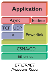
In ETHERNET Powerlink the TCP (and UDP) IP stacks in Layer 3 and 4 are extended by the Powerlink protocol. An additional Middleware is based on TCP (and UDP) IP as well as the Powerlink stack (asynchronous data transfer). Moreover, there is a stack for the fast, cyclic data transfer (isochronous data transfer). The Powerlink stack completely controls the data traffic on the network. The method is called Slot Communication Network Management (SCNM) to provide the real-time capability of Ethernet. Each station has timed and strongly limited communication rights and can send data to each other station within the network. At a particular time only one station can access the bus so collisions are impossible and so achieve strict deterministic performance. In addition to these individual time-slots for isochronous data transfer, the SCNM provides common time-slots for asynchronous data transfer.
An extended version (Version 2) contains communication and device profiles based on CANopen (in cooperation with the CAN in Automation (CiA) group). Version 3 of ETHERNET Powerlink includes time synchronisation mechanisms based on the IEEE 1588.
JetSync
The German company Jetter offers a method of synchronisation via Ethernet TCP/IP which it calls JetSync. It uses processes similar to IEEE 1588 but also supports asynchronous communication. The company claims that its system leads to a more open and flexible structure than that achieved by using strict synchronisation time-slot methods.
JetSync supports motion control applications as well as transmission of ordinary asynchronous data through TCP/IP. This, says the company, achieves compatibility using standard components for communication between PLCs, drives, remote I/O modules and SCADA components. Jetter claims that synchronisation of motion axes to better than 10�s axis jitter can be achieved just using TCP/IP alone running on a standard Ethernet infrastructure.
Modbus/TCP – IDA
The recently merged Modbus-IDA Group is working towards further development of the IDA architecture for distributed control systems using Modbus/TCP for the message structure.
Modbus/TCP is a derivative of the Modbus protocol and the open specification, based on Ethernet and standard TCP/IP, mounts directly on Layer 4. It defines a simple structured, open and widely used transmission protocol for a master-slave communication.
IDA is not only a protocol (like Modbus), but a comprehensive interface that integrates methods for distributed and intelligent automation. The IDA approach takes in the entire architecture of the control system, communication services and device/software interface. It provides both horizontal and vertical integration and makes extensive use of Web Services.
IDA architecture takes account of both real-time as well as non realtime communication. The deterministic aspects will be realised through IDA middleware which is directly mounted on the TCP/UDP stack. The middleware contains the Modbus/TCP protocol as a standard. Non real-time and web-based communication uses the TCP/IP stack. Diagnostics and data programming, parameterisation, etc, for operation of devices and systems will be delivered using the IT standard protocols HTTP, FTP and SNMP. The IDA approach promises a seamless communication architecture (vertical and horizontal) while incorporation of Modbus/TCP opens up the market for a variety of devices such as intelligent sensors.
PROFINET
The first version of PROFINET used Ethernet for non time-critical communication of higher-level devices and Profibus-DP fieldbus technology for real-time domains integrated to a higher level by Proxies.
In its second release, PROFINET provided two communication mechanisms over Ethernet: The standard non real-time communication channel uses TCP/IP while the a second channel bypassing the Layers 3 and 4 of the OSI reference model provides more deterministic communication. The protocol reduces data length in order to minimise the throughput time in the communication stack. For an optimal communication performance PROFINET prioritises the packet as specified in IEEE 802.1p. For real-time communication the highest priority (priority 7) will be used.
PROFINET Version 3 uses a hardware solution to bypass the software- based fast channel shortening throughput time in the communication stack yet further. In connection with integrated switched Ethernet, PROFINET V3 provides a solution for motion control applications based on Isochronous Real-Time IRT, IEEE-1588.
SERCOS-III
SERCOS interface (SErial Real-Time COmmunication System) is a digital interface for communication purposes between controller and drives using an optical fibre ring. The technology was developed by an industrial consortium during the late 1980’s. Now, SERCOS will be promoted and further developed by the IGS (Interessengemeinschaft SERCOS interface).
Real-time behaviour and determinisms will be achieved by using time-slot mechanisms (Time Division Multiplex Access or TDMA). The time-slots allow for transmission of time-critical and non-critical data in alternation. SERCOS was originally developed as drive interface but includes conventional I/O modules as supported devices. SERCOS-III has been designed for Industrial Ethernet. Plans include replacement of the hardware based communication interface with more flexible solutions, for instance in supporting several software based automation protocols and the use of standard hardware components.
Foundation Fieldbus HSE
In addition to the protocols described above, more Ethernet applications, such as HSE – High Speed Ethernet and safeethernet are available. HSE is supported by the Fieldbus Foundation. From a technical point of view HSE operates as a backbone and is interconnected with the underlying fieldbus system (H1 bus) via gateways.
Safeethernet
As a product of the German company HIMA, this protocol uses a network based on standard Ethernet and hence allows the application of standard IT protocols. As the name suggests, application areas include safety-related automation systems.
Christian Schwab is Project Manager at Centre Distributed Systems, University of Magdeburg, Germany, and works within the IAONA Office and the IAONA JTWG System Aspects


