TechnologyJuly 15, 2021
TSN technology: basics of Ethernet Frame Preemption, Part 2

Ethernet Frame Preemption is a new extension to Ethernet. Part of Time-Sensitive Networking (TSN), it guarantees a constant cycle time for industrial applications. Why this extension is necessary, and the way it works is described in two articles. Look for Part 1 online in the June issue of the Industrial Ethernet Book.
In the first article on Frame Preemption , we described how frame preemption can chop a message in smaller fragments, and the receiver assembles them again to re-create the original (long) message. This looks simpler than it sounds, as it is a fundamental change to the Ethernet implementation as it has been for 35 years.
Basic terminology
We have seen that in order to keep the real-time requirements, some messages must have the guarantee that they can be sent in time. In Ethernet terminology, these are called the “Express” messages. All messages not being express messages are labelled “Normal” messages (we called them ‘acyclic’ earlier). Depending on the available time in a cycle, the normal messages can be subject to fragmentation due to preemption. The first fragment of the preemption procedure is called the “Start Fragment”, after which a number of “Continuation Fragments” can follow, followed by the “Last Fragment”.

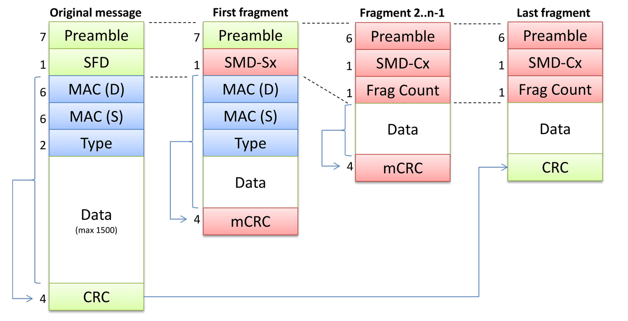
Figure 2: The different three types of fragmented messages as compared to the original Ethernet message format (left). Green and blue fields retain their original value; red fields have different values. The “data” field is not shown to size.
Changes to the message format
The Ethernet message format hasn’t changed much in 35 year, except for the introduction of the VLAN/QoS (4-byte) field. For frame preemption, a much larger change is necessary, needed to store the additional administrative fields. These fields contain the data that the receiver needs to properly handle fragments (first/intermediate/last) in the right order, and detect errors.
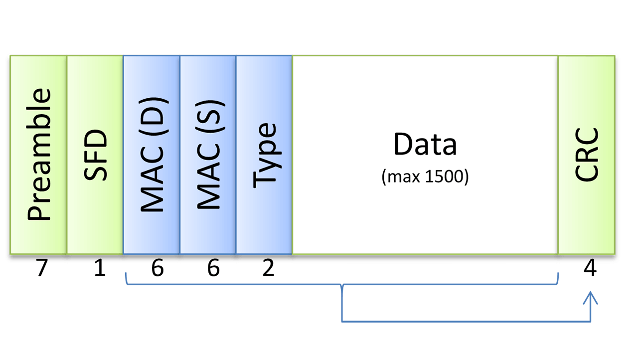
The original Ethernet message format is shown in figure 1. Each message starts with a 7-byte “Preamble”, each byte with value 0x55 (binary 01010101). Following the preamble comes the 1-byte field “SFD” (Start Frame Delimiter), with the fixed value 0xD5. Next comes the sender’s MAC-address (6 bytes), receiver MAC-address (6 bytes), Type field (2 bytes), and up to 1500 bytes of data. The message ends with a 32-bit CRC
For use with frame preemption, the following changes are made (the SFD byte is now called SMD):
- Transmission of “Express” messages. The SMD has value 0xD5 (unchanged).
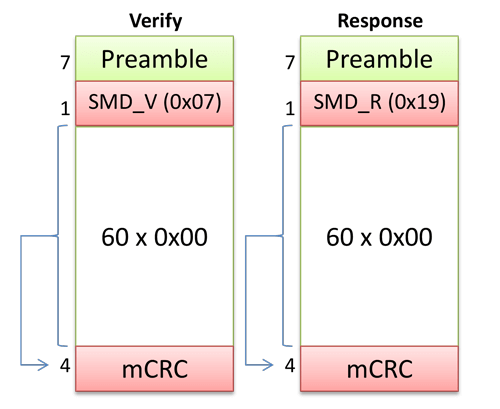
- Transmission of “Verify” and “Respond” bookkeeping messages. The SMD has value 0x07 or 0x19.
- Transmission of the first fragment of a message. The SMD has value 0xE6, 0x4C, 0x7F or 0xB3
A different message format is used for the continuation fragments (2..n-1, if any) of a message, and the last fragment. This requires some additional administration, so the receiver knows how to recognize what it receives. Additionally, it also allows the receiver to detect errors (such as a missing fragment). The SMD-Cx has value 0x61, 0x52, 0x9E or 0x2A (see below for an explanation).
The IEEE has decided to shorten the preamble by one byte; it is now only 6 bytes long. Next comes the SMD, followed by a new field called “fragment counter”. This makes the initial fields (preamble, SMD, fragment counter) again 8 bytes long.
Next comes the data, which is always at least 60 bytes (to satisfy Ethernet timing requirements). Finally we have the CRC field. As usual, the CRC field (in 802.3br renamed to “mCRC”) is calculated over all bytes following the first 8 bytes. Note that the SMD-Sx, SMD-Cx, and the fragment counter, are not covered by the mCRC; therefore additional measures are necessary to detect any errors in these fields.
The least significant 16 bits of the mCRC are inverted just before transmission. However, for the last fragment, the original CRC is used, and the last 16 bits are not inverted. This difference allows the receiver to detect that the last fragment has been received.

Figure 3: The contents of a “Verify” and of a “Response” message.
Backwards compatibility
For any new extension to Ethernet, there is always the question: is it interoperable with older Ethernet equipment? The IEEE has always striven to remain backwards compatible as much as possible. This policy has undoubtedly been fundamental to the popularity of Ethernet, an there is thus also backwards compatibility with equipment that doesn’t support frame preemption (read: almost all Ethernet-devices in the world today).
When two devices do not both support frame preemption, communication errors result. Due to the changed implementation of the message header, and the changed CRC, a receiver would not accept these messages as being valid (and just discard them).
Therefore, when frame preemption is intended to be used, two devices must negotiate this with each other. This is done via a different mechanism than used for auto-negotiation. Here, two specially crafted Ethernet message are used, called a “Verify” and a “Respond” message.
A device that wants to send frame preempted messages first sends a “Verify” message to the other device (at the other end of the cable). When this device sends a “Respond” message back, it states that it also supports frame preemption, and from that moment on it may be used.
Fragment Indication
The most difficult part in frame preemption algorithm is the error handling; any fragment can be lost while ‘in transmission’ on the cable. It must be assured that this is always properly detected.
The receiving device must have some intelligence in recognizing the fragments, as they must be concatenated in the right order. In order to detect this, each fragment is given a “Fragment Counter” (2 bits in size). Following the start fragment (S), the next fragment gets value 0, subsequent fragments increment this counter modulo 4: S,0,1,2,3,0,1,2,3,0,1… etc.
When the receiving device notices the wrong sequence, for example S,0,1,2,0,1,2,3… a fragment has gone missing (3) in this case. Even two fragment may be missed, for example S,0,1,0,1… is still seen as wrong. In case three subsequent fragments are missed this is still detected: S, 0,0,1,2,…
Should 4 subsequent fragments be missed, this is no longer detectable with the fragment counter (S,0,1…), because the receiver does not know the total number of fragments. The only way to detect the missing fragments is that the CRC of the reconstructed message does not match.
When one (or more) fragment(s) are lost, it is not possible to reconstruct the original message. The receiver will wait for the first fragment of the next message. Higher-level protocols (like TCP) will detect the missing message and repair it.
One byte for two bits?
Even though the fragment counter has only 4 possible values, in the Ethernet message it occupies 8 bits. The four possible values are not sent as-is (00,01,10,11) but as 8-bit values 0xE6, 0x4C, 0x7F and 0xB3, respectively. Why is this done? Remember that the fragment count field is not covered by the mCRC. When using only 2 bits, a bit error in transmission could therefore (unknowingly to us) change one valid fragment counter value (say, 01) into another valid bit pattern (11 or 00). This is of course very dangerous.
The 4 values 0xE6, 0x4C, 0x7F and 0xB3 are chosen because of their mathematical property called “Hamming Distance 4”. Changing any of the 8 bits never produces one of the other three values. For example when taking value 0xE6: changing one bit produces either 0x66, 0xA6, 0xC6, 0xF6, 0xEE, 0xE2, 0xE4 or 0xE7, none of which is one of the other three. Even 2 or 3 faulty bits never produces one of the other values. Only when at least 4 bits of any value are inverted one of the listed numbers can result. And even then there is only a ¼ chance that the value for the expected fragment count is produced.
The first fragment
The first fragment of a message is indicated by a special value in the SMD field: a “SMD Start” value SMD-S. When the receiver sees an SMD-S, it knows that it can discard any previously received fragments (if present) and start the assembly of fragments for a new message.
Actually there are four values defined for SMD-S: SMD-S0 (value 0xE6), SMD-S1 (0x4C), SMD-S2 (0x7F) and SMD-S3 (0xB3), values again with HD4. The sender cycles through these four values for every new first fragment. The reason is that the receiver can unambiguously detect that a new first fragment (for a new message) is received.
If a fragment is received which does not contain an SMD-S0, S1, S2 or S3 it is ignored.
Continuation fragments
Continuation fragments of a message are sent according the new message format (figure 2). The SMD field contains a so-called “SMD Continuation” value SMD-C.
Which SMD-C is used depends on the original SMD-S. When it was value SMD-S0, the continuation fragments contain use value SMD-C0; when it was an SMD-S1, the continuation fragments use an SMD-C1, etc. This assures that the receiver always knows to what network message the continuation fragment belongs. This is needed in case of a complete loss of a fragment.
Suppose that in normal circumstances the following fragments are transmitted: (1) SMD_S0, (2) SMD-C0 (first fragment), (3) SMD-C0 (2nd and last fragment), (4) SMD-S0, (5) SMD-C0 (first fragment), (6) SMD-C0 (second fragment), etc.
There are several different error scenarios.
- Suppose that message (3) is completely lost. The receiver now gets an SMD-S again, so it knows a new message is started without the previous message completely having been received. The two fragments are discarded. Ethernet proceeds with processing message (4) and beyond.
- Suppose that messages (3) and (4) are lost. The receiver gets two fragments, both with the same fragment counter. This is not allowed, all received fragments are discarded, processing continues with the next SMD-S in message (7) or later.
- Suppose that messages (3) and (4) and (5) are lost. The receiver gets two fragments with succeeding fragment counters 0 and 1. This is as it is supposed to be! But it is still wrong, as fragments from two different messages are now concatenated.
In order to detect scenario 3, Ethernet gives the second group of fragments a different SMD_S value, i.e. SMD_S1 in our example. On the line we would then see: (1) SMD_S0, (2) SMD-C0 (first fragment), (3) SMD-C0 (2nd and last fragment), (4) SMD-S1, (5) SMD-C1 (first fragment), (6) SMD-C1 (second fragment), etc.
If messages (3) and (4) and (5) are now lost, the receiver gets an SMD-C0 (first fragment) followed by an SMD-C1 (second fragment), so now sees that they belong to two different messages (C0 and C1). The error is now detected.
The last fragment
The number of fragments is not known to the receiver, so how does it know that it has received the last fragment? The fragment counter cannot be used for it, it just counts 0,1,2,3,0,1,2,3… etc. The last fragment is indicated by the 16 least-significant bits of the CRC not being inverted. The receiver can detect this, and so knows it has received all fragments.
Fragment assembly
The receiver concatenates all received fragments as long as the fragment counter (in the message) corresponds to the expected fragment counter. If there is a mismatch, the most likely reason is that a fragment has been lost while in transit, usually caused by data corruption. The receiver then simply discards all received fragments, and starts waiting for a new first fragment (with an SMD-Sx).
With the original CRC in the last fragment, it can also be checked that the concatenation of all received fragments is identical to the original message. If not, the message is discarded.
Rob Hulsebos has been in industrial networks and cybersecurity for more than 30 years.


