

TechnologyJanuary 18, 2024
How to greatly improve battery power efficiency for IoT devices
Addressing the critical role of managing battery power in the exploding world of IoT devices, optimizing ship and sleep mode is one of the best ways to improve battery efficiency. The MAX16163 solution from ADI enables a design with a more precise control over those functions.
Exploring how to make Internet of Things (IoT) devices more power efficient requires a quick refresher of battery management we focus on the critical role of nanopower ship mode and sleep mode. Finally, in this article, we overview a new solution that better optimizes these two aspects of battery management which reduces the power consumption levels and board space over traditional methods.
Introduction
In the connected world of the internet, the IoT plays a crucial role by connecting different sensing nodes and transmitting the data to a secure server. Power management is one of the focus areas to increase the efficiency of the IoT application. In most applications, the sensor node (data acquisition element) is placed in a remote area and powered by a battery. The life of the battery depends on how efficiently we design the power strategies for the sensor node. Most of the time, the sensor node stays in sleep mode and switches to active mode only when it requires data acquisition. The duty cycle of these devices is low. To maximize the battery life, we need to improve the sleep current of IoT applications.

Basics of power management in an IoT device
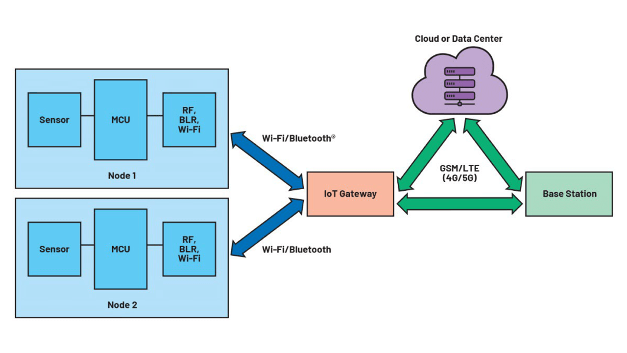
In a typical IoT system, as shown in Figure 1 (above), the wireless sensor node is mostly battery operated and, thus, inherently constrained by battery life. To maximize the life of the sensor node, power management is crucial. The duty cycle concept is a common practice for saving power in a sensor node.
Since overhearing and idle listening are major sources of energy wastage in the sensor node, we can evaluate a wireless sensor node’s power consumption using three different areas:
- Sensor
- Microcontroller
- Radio operation
The sensor collects the raw data like temperature and humidity and sends this data to the microcontroller. The microcontroller processes the raw data and transmits this data to the cloud or data center using a radio link.
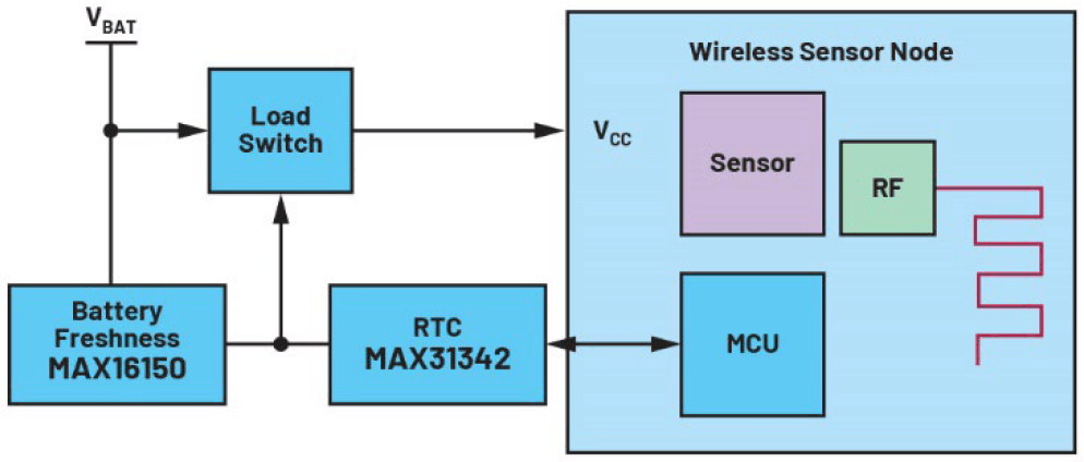
Figure 2. A discrete solution block diagram.
However, given that typical sensor applications operate at very low duty cycles (ranging from 0.01% to 1%) and are idle most of the time, adopting a power management scheme where sensor node sleep current is ultralow will conserve battery life. A smart irrigation system where the sensor node measures the soil moisture and collects data only once per hour is an example of such an application.
Critical roles of ship mode and sleep mode
The ship mode and sleep mode are the common jargon used in battery-operated IoT devices and are crucial aspects of power management in IoT applications. The ship mode is a nanopower state that prolongs battery life during the shipment stage of a product. In ship mode, the battery is electrically disconnected from the rest of the system to minimize power drain while the product is idle or not used. Push-buttons are used to release the ship mode and start the normal operation of the device.
Once the device is in an active condition, sleep mode is used to extend the battery life. In sleep mode, all the peripherals of the system are either shutdown or operating at their minimum power requirement. IoT devices wake up periodically, perform a specific task, and then return to sleep mode.
Different sleep modes can be achieved by disabling various peripherals of the wireless sensor node. For example, in modem sleep, only communication blocks are disabled. In light sleep mode, most of the blocks including the communication block, sensor block, and digital blocks are disabled, and, in deep sleep mode, the wireless sensor node is completely powered off.
Enabling the deep sleep mode in the sensor node can maximize the battery life; therefore, optimizing the deep sleep current is the only way to improve the overall battery life.
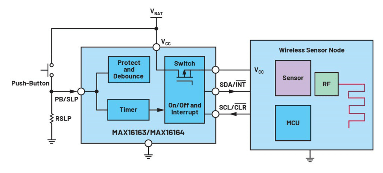
Figure 3. An integrated solution using the MAX16163.
Duty cycling method enables deep sleep mode in IoT applications
Duty cycling in the IoT module is one of the popular techniques for enabling the deep sleep mode. While a wireless sensor node is in deep sleep, most of the peripherals are off or in shutdown mode, consuming only new nanoampere current. A time-keeping device like the real-time clock (RTC) will wake up the IoT module after a programmed timeout.
In this technique, the microcontroller is completely off while the system is in deep sleep mode. However, after recovery, there is always a start-up boot time involved that will add an undesirable delay. Given this trade-off, the impact of the proposed principle depends on the characteristics of each node and the duty cycle of the application.
| Functional Block | Part Number | Sleep Mode Current (nA) (Typ) | Shutdown Current (nA) (Typ) |
|---|---|---|---|
| RTC | MAX31342 | 150 | 6 |
| Load Switch | TPS22916 | 10 | 10 |
| Battery Freshness | MAX16150 | 10 | 10 |
| Total System Current (Typ) | 170 | 26 | |
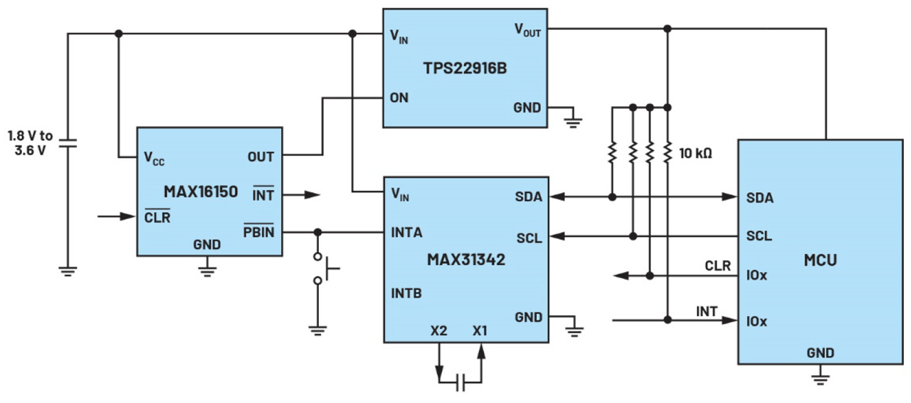
Figure 4. A schematic diagram for a discrete solution.
Conventional solution using RTC, load switch, and push-button controller
In the conventional solution, a load switch and an RTC are used to power on/off the wireless sensor node. In this approach, only the load switch and RTC are active, decreasing the total quiescent current to nanoamperes. The sleep time can be programmed with the microcontroller inside the wireless sensor node.
An external push-button controller can be connected to a load switch to enable the ship mode feature. The external push-button will exit the ship mode and enter the wireless sensor node into normal operation.
Improved solution for deep sleep and ship mode
MAX16163/MAX16164 are nanopower controllers with on/off controllers and programmable sleep time. The devices integrate a power switch to gate an output, which provides up to 200 mA load current. The MAX16162/MAX16163 can replace the conventional load switch, RTC, and battery freshness ICs to save the BOM count and to reduce costs.
The wireless sensor node unit is connected to the battery via MAX16162/MAX16163. The sleep time can be programmed by the microcontroller or can be set using an external resistor from PB/SLP to the ground or using the I2C command from the microcontroller. The external push-button is used to exit the device’s ship mode.
| Specification | Discrete Solution Using MAX31342, MAX16150 and TPS22916 | Integrated Solution MAX 16163 |
|---|---|---|
| Coin Cell Capacity | 250 mAh | 250 mAh |
| Shutdown Current | 146 nA | 30 nA |
| Sleep Current | 170 nA | 10 nA |
| Number of ICs | 3 (RTC + load switch + battery freshness) | 1 (MAX 16163) |
| Crystal Oscillator | Required | Not required |
| Solution Size | 130 mm2 (typical) | 50 mm2 (typical) |
Solution performance comparison
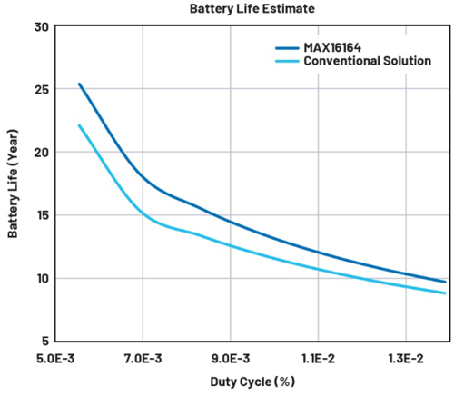
Figure 2. A discrete solution block diagram.
The performance comparison of both schemes is dependent on the duty cycle of the IoT application. In an application with a small duty cycle, the sleep current is a measure of how efficient the system is when the IoT device is running, and the shutdown current is a measure of ship mode power consumption.
To demonstrate the mode of the solution, we have chosen the industry’s smallest quiescent current RTC MAX31342, battery freshness seal MAX16150, and tiny load switch TPS22916. The RTC is programmed using I2C communication that sets the sleep time of the IoT application, and when the timer expires, the interrupt signal pulls down the PBIN pin of the MAX16150, which sets the OUT high and turns on the load switch. During the sleep time, only TPS22916, MAX31342, and MAX16150 consume power system power.
In the experiment, we evaluate the lifetime of two state-of-the-art under fixed duty cycles, comparing their performance of the conventional solution and improved solution using the MAX16163.
The lifetime of the battery can be calculated using the average load current and battery
capacity.
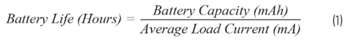
The average load current can be calculated using the duty cycle of the system.
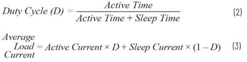
An active current is the system current when the wireless sensor node is active. To compare the two solutions, let’s assume the system wakes up once every two hours, performs the specific task, and enters sleep mode after. The system active current is 5 mA. The battery life depends on the duty cycle of the operation. Figure 5 shows the plot of the battery life of two schemes with different duty cycles, varying from 0.005% to 0.015%.
In summary, this article addressed the critical role of managing battery power in the exploding world of IoT devices. It demonstrated that optimizing ship and sleep mode is one of the best ways to improve battery efficiency. The MAX16163 solution from ADI enables a design with a more precise control over those functions. It extends the battery life by about 20% (for a typical 0.007% duty cycle operation, as seen in Figure 5) and reduces the solution size to 60% as compared to a conventional approach.
Suryash Rai, Product Applications Engineer, Analog Devices