

TechnologyJuly 20, 2023
Automation with remote motion control for intelligent nodes
Industry 4.0 is pushing the boundaries of intelligent automation. Systems solutions are paving the way toward an industrial transformation that promises unprecedented response times along with maximum performance capabilities for motion control.
Industry 4.0 brings the promise of intelligence at the edge over long distances, and 10BASE-T1L Ethernet is paving the way forward with its power over data line (PoDL) capabilities, high data transfer rates, and compatibility with Ethernet-based protocols. This article explains how the new 10BASE-T1L Ethernet physical layer standard can be integrated into automation and industrial scenarios to connect controllers and user interfaces with endpoints, such as multiple sensors and actuators—all using a standard Ethernet interface for bidirectional communication.

Introduction
The 10BASE-T1L is a physical layer standard targeted to industrial connectivity. It offers data rates up to 10 Mbps and power delivery over distances up to 1000 m using a standard twisted pair cable. Low latency and the PoDL capabilities allow devices such as sensors or actuators to be controlled remotely. This article explains how to implement a system composed of a remote host that synchronously controls two or more stepper motors, thereby demonstrating the capabilities of real-time communication over distance.
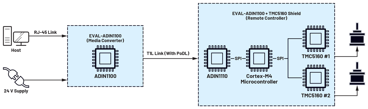
Figure 1. A system overview.
System overview
To begin, the figure above shows a schematic of the system-level application. On the host side, the conversion between standard and 10BASE-T1L links is managed by the ADIN1100 and ADIN1200 Ethernet PHYs, while, on the remote side, the controller interfaces with the link using the ADIN1110 Ethernet MAC-PHY, which only requires an SPI peripheral to exchange data and commands. Precise and synchronized motion control is accomplished by using the ADI Trinamic™ TMC5160 stepper motor controllers and drivers that allow the generation of six-point ramps for positioning without requiring any calculation on the controller.
Choosing these components also keeps requirements on the microcontroller low in terms of used peripherals, computing power, and code size, allowing the use of a wide range of commercially available products. Moreover, up to a predefined power consumption limit, the entire remote subsystem can be directly powered from the data line, so the media converter board is the only module requiring a local power supply.
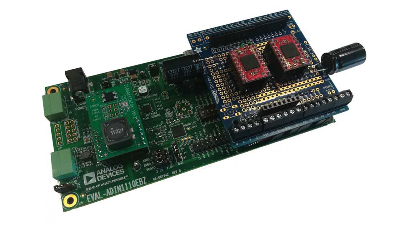
System hardware
The system is composed of four different boards:
The EVAL-ADIN1100 board features an ADIN1200, 10BASE-T/100BASE-T PHY, used in combination with the ADIN1100 10BASE-T1L PHY to translate messages from one physical standard to the other. It can be configured for different modes of operation. In this project, Standard Mode 15 (media converter) is used. The EVAL-ADIN1100 board also features an integrated microcontroller that performs the basic configuration required for media conversion as well as to read diagnostic information. However, it cannot interact with sent and received messages; this board is completely transparent to the communication.
The EVAL-ADIN1110 is the core of the remote devices’ controller. The ADIN1110 10BASE-T1L MAC-PHY receives data through the 10BASE-T1L link and transfers it to an onboard Cortex®-M4 microcontroller via an SPI interface for processing. This board also exposes Arduino Uno-compatible headers that can be used to install a shield to add functionalities to the board.
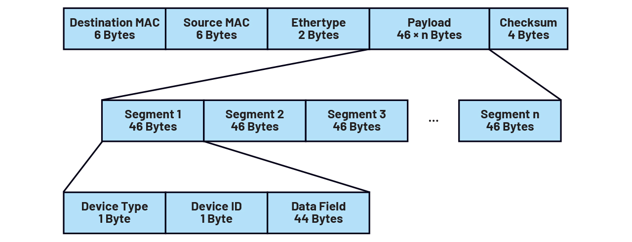
Figure 3. Communication protocol format.
The TMC5160 shield is a custom-developed board based on the Arduino shield form factor. A single shield supports up to two TMC5160 SilentStepStick boards, and multiple shields can be stacked together to increase the maximum number of controlled motors. All the drivers share the same SPI clock and data signals, but chip select lines are kept independent. With this configuration, two communication modes are possible: if chip select lines are asserted individually, the microcontroller can communicate with single controllers—for example, to configure motion parameters. Instead, by asserting more chip select lines simultaneously, all selected drivers receive the same command at the same time.
The latter mode is mainly used for motion synchronization purposes. This board also provides some additional input capacitance to the StepSticks to reduce current peaks at motor startup and to smoothen the current profile during normal operation. This allows the use of PoDL to supply the whole system with a maximum of two NEMA17 motors (with the default setup, the maximum transmitted power is 12 W at 24 V). The board is also used to ease the connection with stepper motors by using screw terminals to make phase outputs from the controllers more accessible.
Two EVAL-ADIN11X0EBZ boards, one for the media converter and one for the EVAL-ADIN1110EBZ, are used to add PoDL capabilities to the system. This board is a plug-in module that can be mounted on the MDI prototyping headers of the evaluation boards and can be configured for both supplying and receiving power from the data line.
Software
The software code is available for download: Remote Motion Control with 10Base-T1L Ethernet – Code.
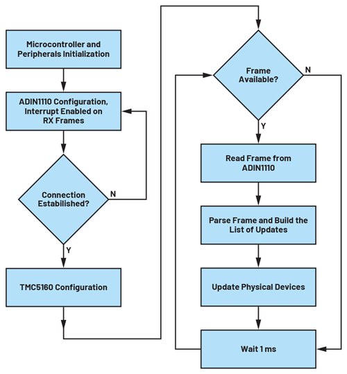
Figure 4. A firmware flowchart.
To keep the code lightweight and minimize communication overhead, no standard communications protocols were implemented above the data link layer. All the messages are exchanged using the payload field of Ethernet frames with a predefined fixed format. Data is organized into 46-byte segments, composed of a 2-byte fixed header and a 44-byte data field. The header includes an 8-bit device type field, which determines how received data is processed, along with an 8-bit device ID field, which enables the selection of an individual physical device if more devices of the same type are present.
The host interface is written in Python to ensure compatibility with both Windows and Linux hosts. Ethernet communication is managed using the Scapy module, which allows creating, sending, receiving, and manipulating packets at each layer of the stack, including the Ethernet data link.
Each device type defined in the protocol has a corresponding class that includes properties to store data to exchange, and a set of methods that can be used to modify these properties instead of having to directly edit the variables. For example, to change motion direction in speed mode for the motion controller, methods “setDirectionCW()” and “setDirectionCCW()” are defined, instead of having to manually assign 0 or 1 values to the direction flag. Each class also includes a “packSegment()” method that packs and returns the segment corresponding to the controlled device in the form of an array of bytes according to the predefined format for the considered device type.
Firmware is written in C using the ChibiOS environment, which includes, among other tools, a real-time operating system (RTOS), a hardware abstraction layer (HAL), and peripheral drivers, allowing the code to be easily ported between similar microcontrollers. The project is based on three custom modules:
ADIN1110.c is the driver used to allow the exchange of data and commands with the ADIN1110 over the SPI interface. It includes low-level communication functions for reading and writing data from device registers, and higher-level functions for sending and receiving Ethernet frames. It also includes the function used to establish communication between 10BASE-T1L transceivers. The pin that notifies if new frames are available is read on interrupt to minimize latency.
TMC5160.c implements all the functions needed to control the TMC5160 motion controller, configured to operate in full-featured motion controller mode. Both constant speed and position control modes are implemented, allowing smooth and precise positioning with six-point ramps. Communication with multiple motion controllers is achieved through a single SPI bus with independent chip select lines. A set of functions and typedefs is also provided to ease motion synchronization.
Devices.c is the interface between data received from the T1L link and physical devices connected to the controller. It includes similar structs to the ones defined in the host interface and functions to update them each time a new frame with valid data is received. This module is also used to determine which actions are executed each time a struct is updated—for example, which physical motion controller is related to commands received at a specific device address.
System Highlights and Validations
This project aims to demonstrate how the new 10BASE-T1L Ethernet physical layer standard can be integrated into automation and industrial scenarios to connect controllers and user interfaces with endpoints, such as multiple sensors and actuators.
This application is targeted to the remote real-time control of multiple stepper motors, widely used in the industry for low power automation tasks, but also utilized in light robots and CNC machines, such as desktop 3D printers, desktop milling machines, and other types of cartesian plotters. However, its use cases can also be extended to other types of actuators and remote-controlled devices. Its main advantages over already existing interfaces used for similar purposes are:
Simplified wiring, requiring only a single twisted pair. The possibility to also deliver power on the data line allows low power devices, such as sensors, to be directly powered from this connection, further reducing the number of required wiring and connectors, and so lowering the complexity, cost, and weight of the overall system.
| Command | Execution Time (ms) | C Cumulative Delay Time (ms) | Optimal Execution Time (ms) |
|---|---|---|---|
| Synchronized motion, two motors (×24 TMC5160 register accesses) | 24.058 | 24.000 | 0.058 |
| Synchronized motion, two motors (×24 TMC5160 register accesses) | 24.058 | 24.000 | 0.058 |
| Dummy data request (no TMC5160 interactions) | 24.058 | 24.000 | 0.058 |
Power delivery using the PoDL standard, which uses a DC voltage superimposed on data lines to supply power to devices connected to the network. This type of coupling can be achieved by only using passive components, and once the voltage on the receiver end is filtered, it can be directly used to power the device or a DC-to-DC converter without requiring rectification. By correctly dimensioning components used for this type of coupling, a high efficiency system can be achieved. In this project, using standard components installed on the evaluation boards leads to an overall efficiency of about 93% (with a 24 V supply and total load current of 200 mA). However, this result has a wide margin for improvement—indeed, most of the losses are due to resistive drops of the passive components along the power path.
Versatility, as it can be used for both last-mile and end-point connectivity. Analog Devices 10BASE-T1L devices have been tested for distances up to 1.7 km. They also allow daisy-chaining with a low impact on system complexity. For example, by using the ADIN2111 two-port low complexity switch, it is possible to design devices that integrate daisy-chaining capabilities, making the link suitable also for end-point nets.
Easy to interface with existing equipment that already integrates an Ethernet controller, including personal computers and laptops. Data frames follow the Ethernet data link standard, and all Ethernet-compatible protocols can be implemented above it, so only a media converter is needed as a bridge with standard Ethernet links. For example, the board used in this project, the EVAL-ADIN1100, can be used as a reference design for a transparent media converter, requiring only two Ethernet PHYs and an optional microcontroller for configuration and debugging.
High data rate, reaching up to 10 Mbps, full duplex. This, combined with the daisy-chain topology on which industrial Ethernet-based protocols can be implemented, allows it to be used in a real-time application, where deterministic transmission latency is required.
Isolation between the transceiver and media can be achieved with both capacitive or magnetic coupling, depending on the safety and robustness requirements of the application.
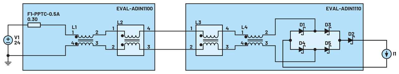
Figure 5. A simplified scheme of power path.
Multiple measurements were done on the system to evaluate its performance. All the peripherals used to communicate with the ADIN1110 transceiver and TMC5160 controllers were configured for the maximum possible speed that is reachable with the standard hardware configuration.
onsidering the 80 MHz system clock of the microcontroller, the data rate of SPI peripherals was set to 2.5 MHz for the motion controllers and to 20 MHz for the ADIN1110 transceiver. For the TMC5160, by tuning the microcontroller clock configuration and supplying an external clock signal to the IC, SPI frequency can be further increased up to 8 MHz, while for the ADIN1110 the maximum limit by data sheet is 25 MHz.
For the latency, the total time between a data request and the reception of the answer frame has been evaluated at about 4 ms (average on 500 samples, measured with the Wireshark protocol analyzer computing the difference between the timestamps of data requests and corresponding answers). Additional evaluations were made to determine which parts of the system are responsible for this delay. Results showed that the main cause is the delay function provided by the RTOS, which allows a minimum delay of 1 ms, used to set the interval between write and read operations for the TMC5160, while the required delay is in the order of tens of nanoseconds. This could be improved by defining a different timer-based delay function that allows for shorter delay intervals.
The second cause of this delay is the Scapy function used to receive frames, which requires a minimum set-up time of 3 ms after it has been called. In a real-world application, this can be improved by developing the interface directly with network adapter drivers for the operating system, instead of third-party tools like Scapy. However, drawbacks include losing compatibility with different operating systems and increasing code complexity.
Precise execution times for the callback implemented on the microcontroller were measured by toggling a GPIO and measuring the high period with an oscilloscope. Measured execution time includes functions used to read and parse received frames and to send commands to motion controllers.
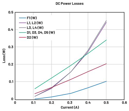
Figure 6. Power losses for each passive component, as a function of current.
The second set of measurements was made to evaluate power losses along the transmission path when using PoDL to supply remote devices. Tests were conducted by substituting the motion controller shield with an electronic load set at different currents, starting from 0.1 A up to 0.5 A in steps of 100 mA, to determine which components had a major impact on power losses and, consequently, how to improve the design to achieve higher current ratings.
The results show that a major contribution to the losses is given by the bridge rectifier along with the Schottky diode D2, both used for reverse polarity protection. Both components could be replaced with a similar circuit based on MOSFET transistors and an ideal diode controller to gain higher efficiency without losing this type of protection. At higher currents, the contribution of the DC resistance of the coupled inductors used for input and output supply filtering becomes dominant, so to improve current capability, similar inductors with higher current ratings are also needed.
Conclusion
Industry 4.0 requirements are pushing the boundaries of intelligent automation. ADI Trinamic technology used along with the ADIN1100, ADIN1110, and 10BASE-T1L transceivers enable the remote control of sensors and actuators up to 1700 m from their controller without requiring power at the edge.
With a reliable method of remote control, stepper motors can easily be controlled in real-time at longer distances without sacrificing any performance or speed. Systems solutions are paving the way toward an industrial transformation that promises unprecedented response times along with maximum performance capabilities.