

TechnologyJanuary 18, 2024
Constrained EtherNet/IP for on-machine sensor networks

An OMSPE sensor network concept enables EtherNet/IP connectivity from sensor to controller and compute. It also enhances the current DLR protocol with new linear network discovery and commissioning functions to simplify the OMSPE sensor network discovery, commissioning, and diagnosis.
Since IEEE802.3cg task force completed the 10BASE-T1S and 10BASE-T1L Ethernet standard development in September 2019, ODVA started its own adoption of these Ethernet technologies. In- cabinet EtherNet/IP usage profile based on 10BASE-T1S Ethernet and Ethernet-APL Instrument profile based on 10BASE-T1L Ethernet have been introduced into the EtherNet/IP Specification.
This article discusses another potential EtherNet/IP usage profile: the On-Machine sensor EtherNet/IP usage profile. A couple of thoughts on the constrained EtherNet/IP On-Machine Single Pair Ethernet (OMSPE) sensor network are explored, including the OMSPE system architecture (the physical topology, the media, the infrastructure taps, the SPE sensor), the communication architecture, the power delivery architecture, and the DLR Plus (DLR+) protocol with the network discovery, commissioning, and diagnosis function etc.

With the sensor supporting the constrained EtherNet/IP connectivity, it not only simplifies the communication technology from the sensor to controller for the traditional industrial control use cases, but also opens new opportunities for the information analytics use cases with the direct communication channel from the sensor to the compute/cloud. As a result, this will add value to the ODVA technology adopters. Most of the concepts discussed have been proved to work within the scope of research prototyping.
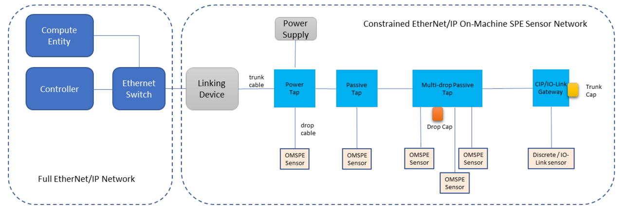
Figure 1 – An On-Machine SPE Sensor Network in an Automation System.
Constrained EtherNet/IP on-machine SPE sensor network
One of the main objectives for the OMSPE sensor network architecture work is to optimize the system cost of the OMSPE sensor network to enable a cost-effective and competitive solution on the market. Several concepts are adopted to support this objective: using passive taps instead of 3-port SPE switch taps to reduce the cost of taps and the system cost, adopting low cost EtherNet/IP concepts used in the In-Cabinet EtherNet/IP usage profile into the OMPSE sensor, using standard 2-pair Ethernet media on the drop, using unshielded cable, using powered SPE technology on the drop, …
Figure 1 illustrates a constrained EtherNet/IP OMSPE sensor network in an industrial automation system. The OMSPE sensor network adopts the trunk-drop physical topology. There are different types of taps connected with the trunk media from the trunk. OMSPE sensors are connected to the drop port of taps with the drop media. Caps are used to terminate the trunk and the unused drop ports on taps. Power is provided to the network via the Power Tap. The OMSPE sensor network is connected to the full EtherNet/IP network via a Linking Device.
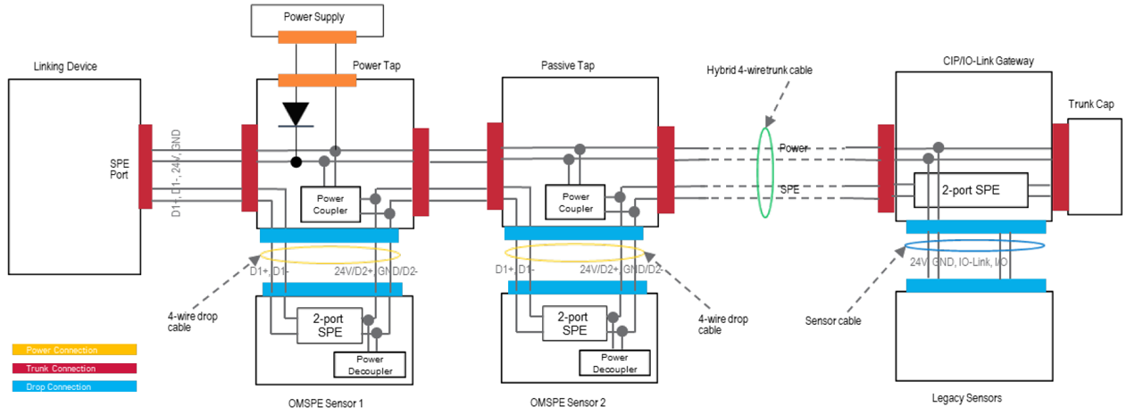
Figure 2 – On-Machine SPE Sensor Network System Architecture.
Figure 2 further details the system architecture for the OMSPE sensor network. A linear SPE network and a bus power network are deployed in principle. The powered SPE technology is adopted on the drop. All OMSPE sensors are connected in a linear network topology via the OMSPE sensor network infrastructure (i.e., the SPE pair of taps and trunk/drop media). The power is provided from the power supply to OMSPE sensors in a bus topology via the OMSPE sensor network infrastructure (i.e., the power pair of the trunk and the powered SPE pair on the drop). The OMSPE sensor network combines the merits of In-cabinet T1S network (low cost EtherNet/IP) and APL/T1L instrument network (powered SPE, long distance SPE) to address the constrained OMSPE sensor use cases.
Active tap (i.e., 3-port switch) approach was considered initially. Reviewing the target system costs (device + network + installation) we concluded that while an active tap removes cost from the sensor (2 PHYs to one PHY and simplified connector), total cost of deployment (2 PHYs to 4 PHYs for connecting single sensor, more complex network commissioning and diagnosis) would increase.
We therefore elected to focus on the passive tap approach rather than the active tap approach. The primary disadvantage is that when a sensor fails, all downstream sensors are unable to communicate. The same is true for the active three-port switch tap component. Further, target applications are likely to be dependent on the failed sensor and unlikely to be able to operate in the case of a failed sensor. Other applications can still be served by classical star topologies.
Network components
The following OMSPE sensor network components are described in detail: Linking Device, Power Tap, Passive Tap, OMSPE Sensor, Trunk Media, Drop Media, End Cap and Drop Cap.
Linking device
The primary functions of Linking Device are:
- As a media converter, to convert between SPE and standard 4-pair Ethernet,
- As a LNDC manager, to perform network discovery, commissioning, diagnostic, …,
- As a protocol converter, to convert between TCP/TLS and UDP/DTLS,
- As a security proxy to authorize the user permissions/access rights on behalf of sensors,
- As a CIP router, to integrate two EtherNet/IP transport profiles seamlessly,
- As an I/O connection aggregator, to reduce number of I/O connections for controller.
Power Tap
The primary function of Power Tap is to inject the power from the power supply to the OMSPE sensor network.
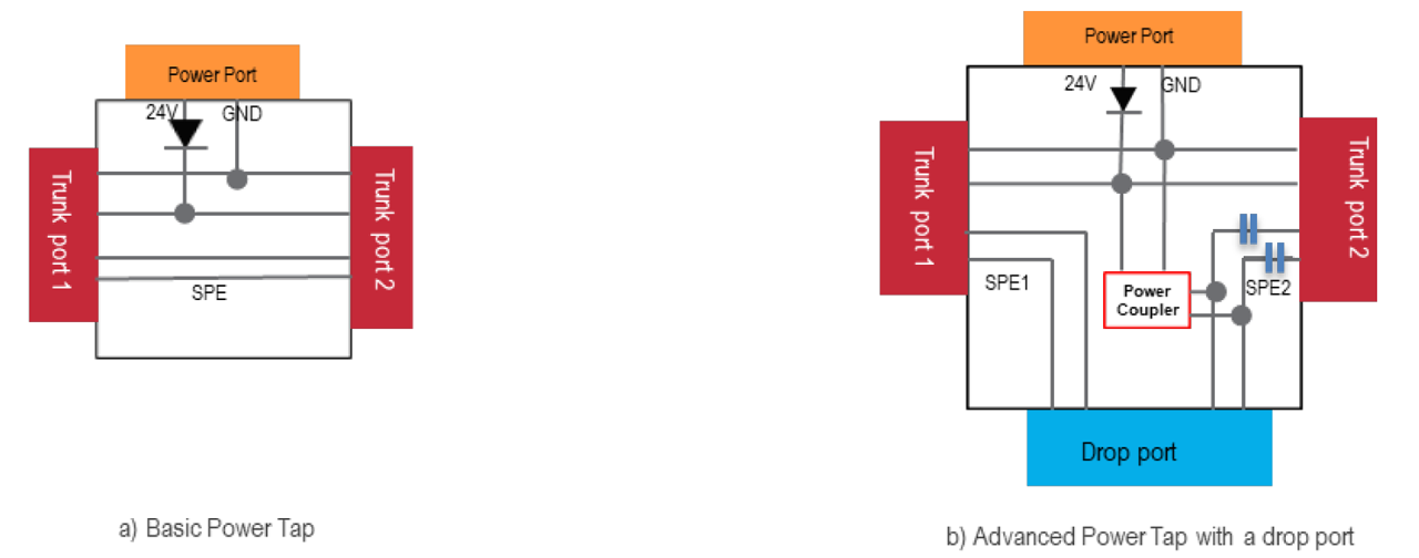
Figure 3 – Power Tap Architecture.
The basic power tap (as shown in Figure 3 a) has one power port and two trunk ports. The power port is connected to the power source (e.g., a 24V DC power supply). The 24V DC power is injected to the trunk power pair of the OMSPE sensor network. A diode on the 24V line prevents the current loop in the case that multiple power taps are used on an OMSPE sensor network. The first trunk port of the power tap is connected to the upstream trunk cable, and the second trunk port of the power tap is connected to the downstream trunk cable. The power tap delivers the power to the upstream and downstream network through two trunk ports. The power tap passes through the SPE signal from the first trunk port to the second trunk port.
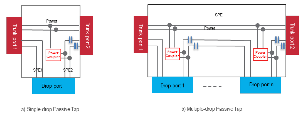
Figure 4 – Passive Tap Architecture.
The advanced power tap as shown in Figure 3 b) has an additional drop port. Besides the power injection function, it also can connect one OMSPE sensor onto the network via this drop port. Different from the basic power tap, the advanced power tap connects the upstream SPE pair (SPE1) and the downstream SPE pair (SPE2) to the drop port for connecting the OMSPE sensor. In addition to delivering power to the upstream and downstream network, the advanced power tap couples the power from the trunk power pair to the drop SPE2 pair via a power coupler. Two capacitors on the SPE2 pair between the power coupler and the second (downstream) trunk port prevent the power from flowing to the downstream network.
Passive tap
The primary function of a passive tap is to connect the OMSPE sensor to the OMSPE sensor network.
The single drop passive tap as shown in Figure 4 a) has two trunk ports and one drop port. The first trunk port of the passive tap is connected to the upstream trunk cable, and the second trunk port of the passive tap is connected to the downstream trunk cable. The single drop passive tap connects the upstream SPE pair (SPE1) and the downstream SPE pair (SPE2) to the drop port for connecting the dual-port OMSPE sensor. The single drop passive tap passes through the power from the first trunk port to the second trunk port and couples the power from the trunk power pair to the drop SPE2 pair via a power coupler.
Two capacitors on the SPE2 pair between the power coupler and the second (downstream) trunk port prevent the power from flowing to the downstream network.
For a multiple drop passive tap as shown in Figure 4 b), each individual drop port has a power coupler and associated capacitors for the powered SPE operation on the drop.
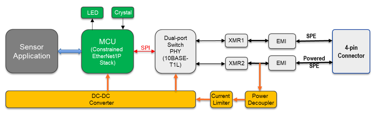
Figure 5 – OMSPE Sensor Function Block Diagram.
OMSPE sensor
Figure 5 illustrates a block diagram for an OMSPE sensor as an implementation example. Conceptually, the OMSPE sensor circuitry consists of four parts: MCU, SPE, power, and sensor application. MCU, SPE and Power circuitries are common while the sensor application circuitry is product specific.
The SPE circuitry has upstream and downstream SPE communication channels. Each SPE communication channel is designed with an industrial level front end interface circuitry by having an EMI protector/filter and a SPE signal transformer. A single chip with a 3-port embedded switch, dual 10BASE- T1L PHYs and a SPI host interface is used for low cost and small footprint design. A single 4-pin standard M12-D Ethernet connector is used for both upstream and downstream SPE signal connections, which is different from the normal dual port EtherNet/IP device.
The downstream SPE pair also carries 24V DC power. A power decoupler module separates the power from the SPE communication signal. A current limiter limits the maximum current consumed from the OMSPE sensor network in the case of a short circuit fault, which minimizes the impact on the OMSPE sensor network.
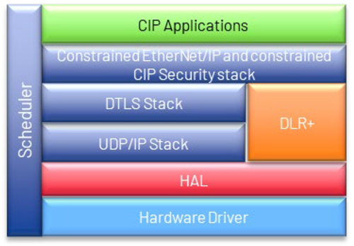
Figure 6 – Constrained EtherNet/IP Stack for OMSPE Sensors.
A low-cost non-Ethernet MCU (no MII/RMII) is used to reduce the cost. Standard OPEN Alliance SPI protocol is used between the MCU chip and the switch-PHY chip. Constrained EtherNet/IP stack as shown in Figure 6 is deployed.
The constrained EtherNet/IP stack conforms to the ODVA UDP-only transport profile and constrained CIP Security profile. The constrained EtherNet/IP stack may operate with a Scheduler instead of RTOS to reduce the memory consumption. The DLR+ protocol is also contained in the stack to support the network discovery, commissioning, and diagnosis functions.
Trunk media
The trunk media of the OMSPE sensor network are hybrid SPE cable and connector. The hybrid SPE cable has one power pair and one SPE pair. The power pair must endure at least 4A DC current so its gauge should be AWG18 or thicker. The SPE pair should be twisted and separated from the power pair in the cable. The electrical parameters of the SPE pair shall meet the IEEE PHY link segment specification. If possible, the trunk cable is preferred to be unshielded, and the trunk connector is preferred to be M12 4-pin connector.
Drop media
The drop media of the OMSPE sensor network are standard unshielded 2-pair Ethernet cable and 4-pin M12-D Ethernet connector. One pair is used for the SPE communication, and the other pair is used for the SPE communication and power delivery.
Trunk cap
The trunk cap is installed on the last tap’s downstream trunk port. There is no electronic termination in the trunk cap.
Drop cap
The drop cap is installed on a drop port reserved for future use. The drop cap connects the first SPE pair to the second SPE pair on the drop port via internal capacitors, which prevents the power on the second SPE pair from flowing back to the first SPE pair.
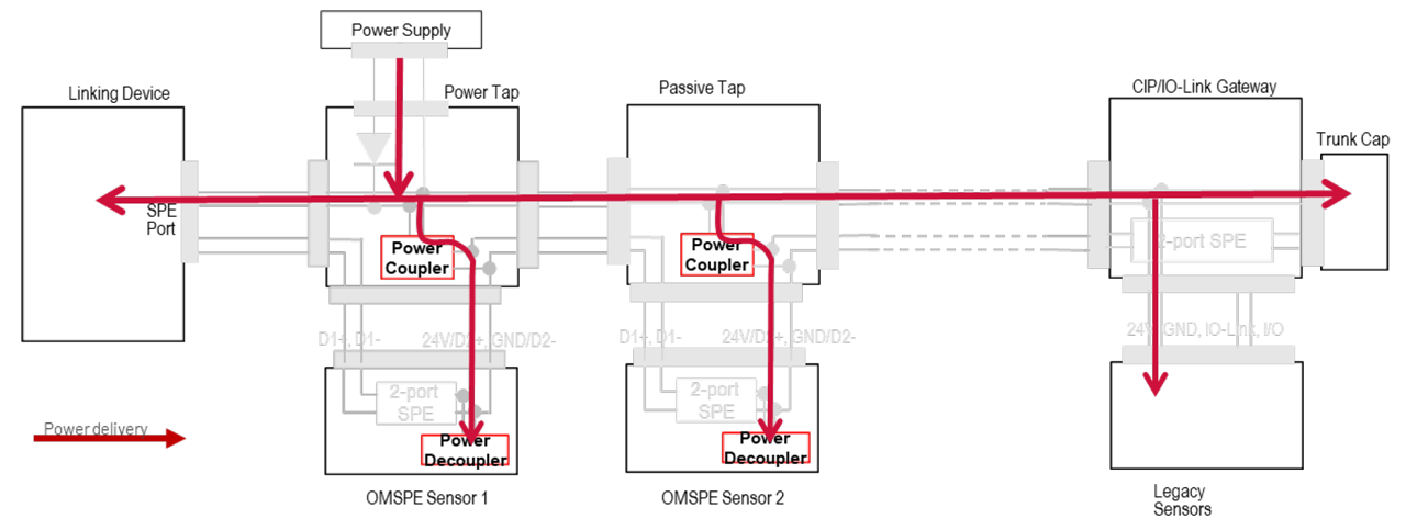
Figure 7 – OMSPE Sensor Network Power Architecture.
Power Architecture
As shown in Figure 7, the OMSPE sensor network distributes the power on the power pair of the trunk media and delivers the power to each drop via the powered SPE concept. The powered SPE concept requires a power coupler in the passive tap and a power decoupler in the OMSPE sensor. The power coupler in the passive tap couples the power from the trunk power pair to the drop SPE pair. The power is delivered to the OMSPE sensor via the powered SPE pair. The power decoupler in the OMSPE sensor decouples the power from the SPE pair and provides the power to the OMSPE sensor’ circuitry. Two adjacent OMSPE sensors communicate over the same SPE pair on this drop. Two capacitors in the passive tap are used to prevent the power from flowing to the adjacent OMSPE sensor.
This powered SPE architecture enables the use of standard 2-pair Ethernet drop cable and connector. The power coupler/decoupler circuitry (power inductor) is small and low cost since the power coupler/decoupler only needs to pass the current for a single OMSPE sensor (0.5W).
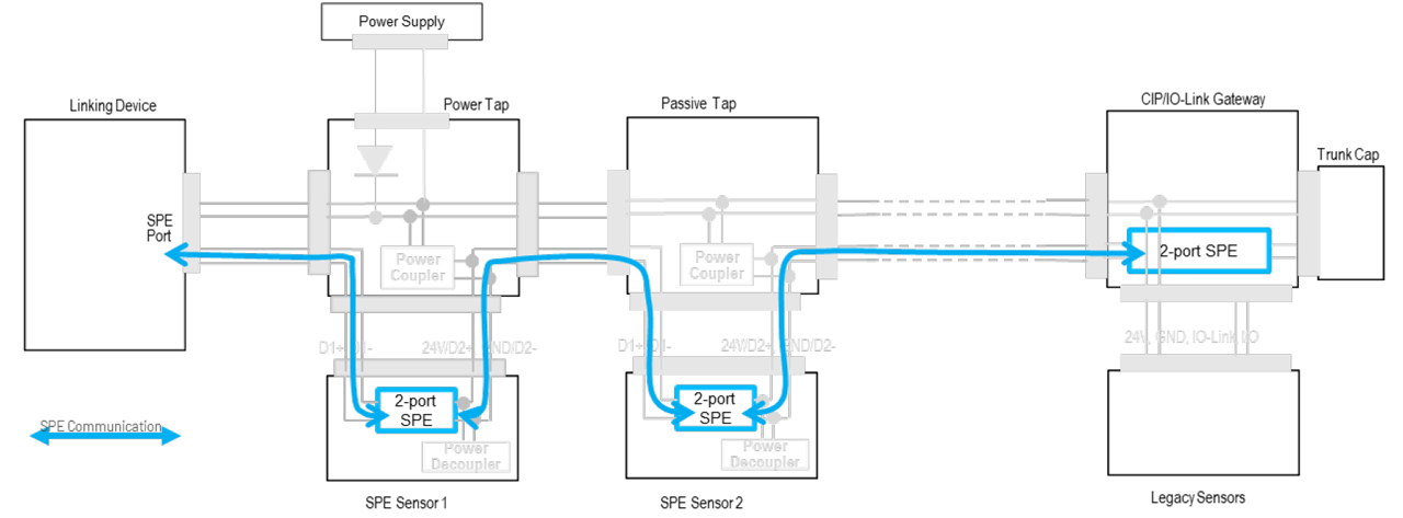
Figure 8 – OMSPE Sensor Network and Communication Architecture.
Communication architecture
As shown in Figure 8, the SPE sensors are connected in a linear topology from the SPE communication point of view. Each OMSPE sensor has dual SPE ports. The first SPE port communicates with the upstream device and the second SPE port communicates with the downstream device.
The SPE link segment between two OMSPE sensors may consist of a trunk media, two trunk taps, and two drop media. The SPE link segment between the first OMSPE sensor and the linking device consists of one trunk media, one drop media and one trunk tap.
Sensor to controller communication
IO-Link is the current most popular communication technology for sensors. To integrate IO-Link Sensor with EtherNet/IP Controller, a specialized EtherNet/IP to IO-Link gateway function is required to translate between IO-Link and EtherNet/IP protocol and map between CIP and IO-Link data.
With the OMSPE sensor network, the sensor to controller communication is simplified because the OMSPE sensor natively communicates with EtherNet/IP. There is no complexity of the application protocol translation and data mapping.
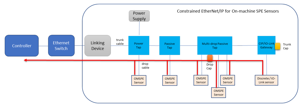
Figure 9 – Sensor to Controller Communication.
Sensor to “compute” communication
With the OMSPE sensor network, the sensor to “compute” communication is simplified too compared to IO-Link technology. Because the OMSPE sensor uses IP and Ethernet communication, it is easy to add IIOT protocols into the sensor (e.g., MQTT). It could also use EtherNet/IP to communicate with a “compute entity” such as HMI, Workstation, or Edge device for Cloud. Direct access to rich sensor information such as sensor identity, configuration, and diagnostics enables new data analytic use cases.
DLR+ with LNDC functions
The protocol to simplify the OMSPE sensor network discovery, commissioning, and diagnosis is studied to support the objective of delivering the “ease of use” user experience.
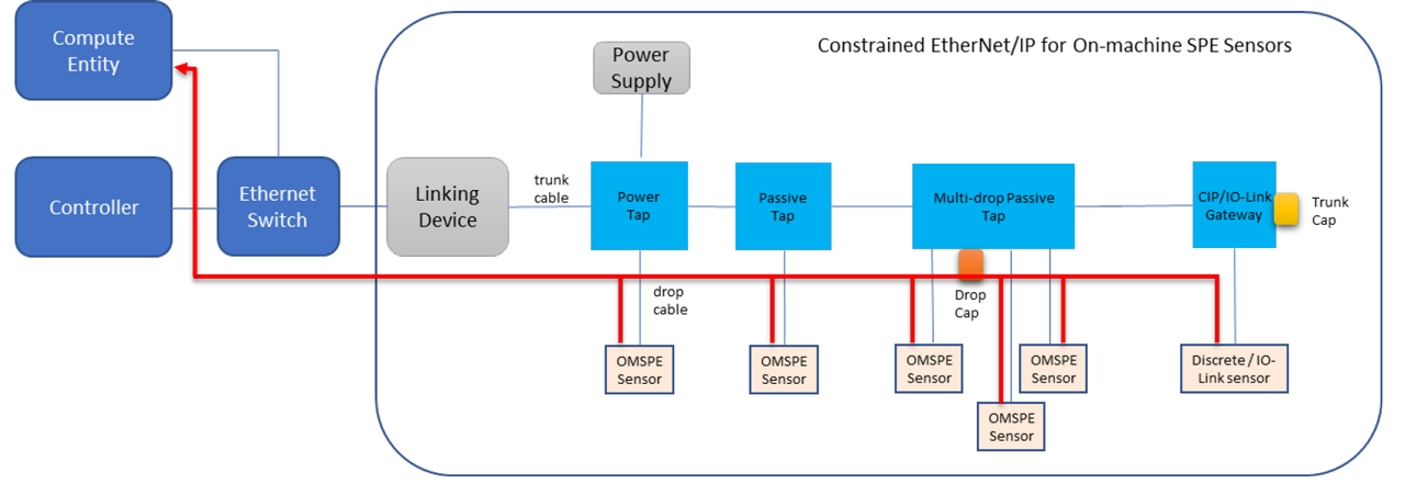
Figure 10 – Sensor to Compute Communication.
LLDP is a link layer discovery protocol, which is used for the network topology and device capabilities discovery. DHCP is a dynamic host configuration protocol, which is used for the device IP and network configuration. Using LLDP and DHCP for the OMSPE sensor network discovery, commission and diagnosis were considered at the beginning, however a couple of challenges are identified:
- LLDP is a link layer protocol. It would be quite complex to discover the location of the sensor on the network by the LLDP messages because the OMSPE sensor network is a switch-based linear network where LLDP messages are not allowed to cross the switch for the sensor position discovery.
- Knowing the whole topology by the linking device needs to read all Data Table objects in Sensors. This assumes the IP address is assigned in Sensors, however at this stage, the IP address is not determined.
- When the network changes (sensor insertion, removal, replacement), it will be quite difficult to detect these changes by the linking device because the LLDP messages from that device cannot reach the linking device. This will complicate the user experiences on the network diagnosis and the network upgrade.
DLR is a link layer protocol for the linear and ring network operation. Enhancing DLR with Linear Network Discovery and Commissioning (LNDC) functions to address the OMSPE sensor network use cases is proposed.
In specific, LNDC provides the following functions:
- Discover the network topology and apply it as reference topology,
- Commission the network easily including the initial network configuration and network device replacement,
- Diagnose the network quickly by detecting the device insertion, removal and change at a specific location.
The enhanced DLR protocol (DLR+) is also applicable to a general linear EtherNet/IP network.
EtherNet/IP In-Cabinet Usage Profile has already specified a network topology discovery and commissioning protocol for 10BASE-T1S multi-drop EtherNet/IP network. Main concepts of In-cabinet Actual topology object (discover current network topology, detect the changes to the last discovered topology) and In-cabinet Commissioning object (sync the reference topology, allocate IP address for devices, detect the topology change) are reused for the OMSPE sensor network.
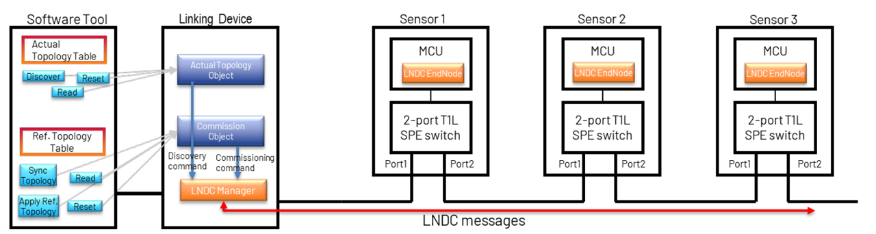
Figure 11 – LNDC Protocol Architecture.
As shown in Figure 11, there are four primary LNDC entities in an OMSPE sensor network: Software Tool, CIP Objects, LNDC Manager and LNDC End Node. The LNDC Software Tool provides user interfaces to display the actual topology information and the reference topology information and to issue the discovery and commissioning commands to the OMSPE sensor network. The Actual Topology object and Commissioning object in the Linking Device provides discovery and commissioning services to the LNDC Software Tool. The LNDC Manager initiates the discovery and commissioning process on the OMSPE sensor network under the commands from the Actual Topology object and Commissioning object. The LNDC End Node reports its network information in response to the Discovery Topology request and applies the network configuration retrieved from the Commissioning request message and responds with the state code indicating the configuration is successful or not.
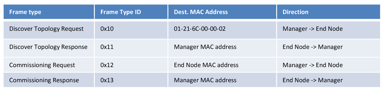
As shown in the table below, the new DLR messages Discovery Topology and Commissioning are defined for LNDC functions. All messages use the Ring EtherType (0x80E1) and Ring protocol Subtype (0x02). The Discovery Topology Request is a multicast message. All LNDC End Nodes shall receive and process this message. All other three messages are unicast messages.
Discover network
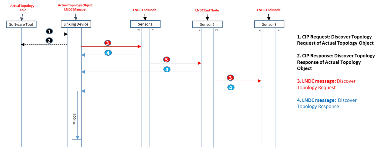
Figure 12 – LNDC Network Discovery.
Figure 12 illustrates the message sequences among LNDC entities for the network discovery process.
- The LNDC Software Tool sends a CIP Discover Topology request to the Actual Topology object in the Linking Device.
- The Actual Topology object replies to the LNDC Software Tool with a CIP Discover Topology response.
- The Actual Topology object notifies the LNDC Manager to start the network discovery.
- The LNDC Manager generates a Discover Topology Request message with a multi-cast MAC address (01-21-6C-00-00-02) and initial position ID (1) and sends the Discover Topology Request to the first OMSPE sensor on the OMSPE sensor network. The position ID indicates the location of the OMSPE sensor in the logical linear SPE network. The linking device always has the position ID 0, the first sensor following the link device has the position ID 1, the second sensor following the first sensor has the position ID 2, etc. The LNDC Manager also starts the discovery timer with 500ms timeout value. The discovery timer is used to determine the completion of the discovery process.
- The LNDC End Node in the first OMSPE sensor generates a Discover Topology Response message with the OMSPE Sensor’s position ID, MAC address, IP address, and CIP product key in response to the received Discover Topology Request message and sends the Discover Topology Response message to the LNDC Manager, then increases the position ID and forwards the Discover Topology Request message to the second OMSPE sensor.
- The LNDC End Node in the second OMSPE sensor generates a Discover Topology Response message with the OMSPE Sensor’s position ID, MAC address, IP address, and CIP product key in response to the received Discover Topology Request message and sends the Discover Topology Response message to the LNDC Manager, then increases the position ID and forwards the Discover Topology Request message to the third OMSPE sensor.
- Step 6 repeats one by one until the last OMSPE Sensor is discovered.
- The LNDC Manager completes the network discovery once the 500ms discovery timer expires. The discovery timer is reset whenever a Discovery Topology Response message is received. So, the discovery timer will not expire until the last OMSPE sensor is discovered.
- The LNDC Manager checks the integrity of the discovered topology information. An error is reported if there is a gap in the actual topology table or the number of nodes is not equal to the actual topology table size.
Commissioning network
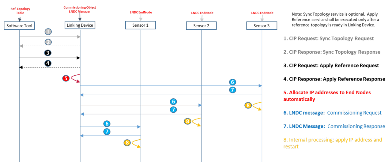
Figure 13 – LNDC Network Commissioning.
Figure 13 illustrates the message sequences among LNDC entities for the network commissioning process.
- The LNDC Software Tool sends a CIP Sync Topology request to the Commissioning object in the Linking Device.
- The Commissioning object replies to the LNDC Software Tool with a CIP Sync Topology response and retrieves the actual topology information from the Actual Topology object and sets it as the reference topology. Note that the reference topology in the Commissioning object might be generated by the user configuration instead of the discovered actual topology.
- The LNDC Software Tool sends a CIP Apply Reference Topology request to the Commissioning object in the Linking Device.
- The Commissioning object replies to the LNDC Software Tool with a CIP Apply Reference Topology response.
- The Commissioning object automatically allocates IP addresses for the end nodes whose IP addresses are not configured and notifies the LNDC Manager to start the network commissioning.
- The LNDC Manager generates a Commissioning Request message with the allocated IP address in the Commissioning object for the last OMSPE Sensor and sends the Commissioning Request message to the last OMSPE Sensor on the OMSPE sensor network.
- The LNDC End Node in the last OMSPE sensor generates a Commissioning Response message with the status code in response to the Commissioning Request message and then applies the IP address and other configurations internally.
- After the LNDC Manager receives the Commissioning Response, it generates another Commissioning Request message with the allocated IP address in the Commissioning object for the penultimate OMSPE Sensor node and sends the Commissioning request to the penultimate OMSPE Sensor on the OMSPE sensor network.
- The LNDC End Node in the penultimate OMSPE Sensor generates a Commissioning Response message with the status code in response to the Commissioning Request message and then applies the IP address and other configurations internally.
- Step 6-7 repeats one by one in reverse order until the first OMSPE Sensor is commissioned.
Diagnose network
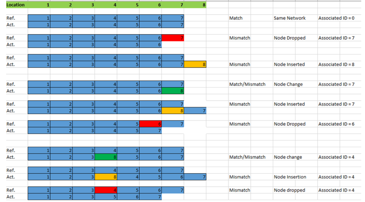
Figure 14 – LNDC Network Diagnosis Scenarios.
The LNDC manager can detect the network changes (node removal, insertion, and change) by comparing the reference topology to the current actual topology. Figure 14 LNDC – Network Diagnosis Scenarios, where the reference topology and actual topology are compared and the corresponding network diagnosis result are derived.
For a device replacement case (node change), the network match/mismatch is reported by comparing the product key of the old device to the product key of the new device based upon the key matching criteria. If a compliant device is replaced, the same IP address (and device configuration) is applied.
For a system upgrade case (node inserted), a network mismatch is always reported. The new devices’ IP address will be automatically allocated by the commissioning object and assigned to the new devices inserted onto the network.
For a device fault case (node dropped), a network mismatch is always reported.
For all above cases, the associated position ID is reported. The user can easily identify the location of the node removal, insertion, and change.
LNDC software prototype
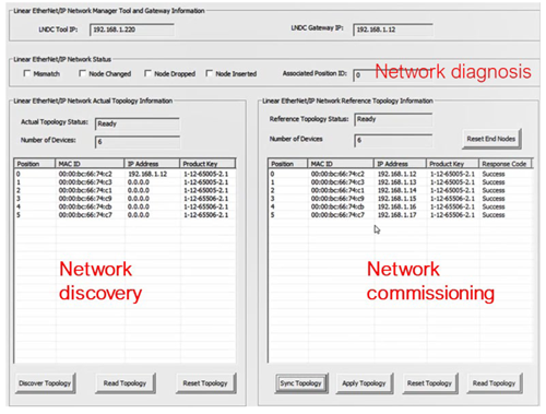
Figure 15 – LNDC Software Tool Prototype
Figure 15 illustrates a LNDC software prototype.
In the network discovery area, the user can start the network discovery process by clicking the “discover topology” button. The discovery results are shown in the table. Each node has the position, MAC ID, IP address and CIP product key displayed at a row. The IP address 0 or a default IP address value is shown if the device is not commissioned. The number of devices on the network and the current network topology status are shown above the actual topology table. The user can also reset or retrieve the network topology by clicking the “reset” or “read” button.
Figure 15 – LNDC Software Tool Prototype
In the network commissioning area, the user first syncs the reference topology to the actual topology by clicking the “Sync” button after the current network topology has been discovered. The IP addresses will be automatically allocated for devices whose IP addresses are not assigned. The user then applies the reference topology to the network by clicking the “Apply Topology” button. During this process, the IP addresses will be commissioned to the devices. The user can also reset or retrieve the reference network topology by clicking the “reset” or “read” button.
During the operation, the LNDC manager might periodically monitor or detect the network change. The network diagnostics information (network mismatch, node changed, node inserted, node removal, and associated position ID) is displayed in the network diagnostic area.
Summary and outlook
An OMSPE sensor network concept enables EtherNet/IP connectivity from sensor to controller and compute. It also enhances the current DLR protocol with new linear network discovery and commissioning functions to simplify the OMSPE sensor network discovery, commissioning, and diagnosis.
Most of the concepts have been proved to work within the scope of research prototyping. Further collaborations on this topic within the ODVA community are expected, in the areas of concept optimization for product design, specification enhancements on On-machine sensor EtherNet/IP usage profile and the whole ecosystem development. The optimization and enhancement should focus on the system cost optimization and ease of use, such as achieving reliable communication with the unshielded cable, developing highly integrated low-cost dual-port T1L SPE chip and minimizing the user configuration of the network, etc.